Mitsubishi 380. Manual - part 775
SRS AIR BAG DIAGNOSIS
SUPPLEMENTAL RESTRAINT SYSTEM (SRS)
52B-24
DIAGNOSTIC TROUBLE CODE PROCEDURES
DTC B1400: Driver’s Air Bag Module (1st Squib) System Fault 1 (Short Circuit between Terminals of
the Squib Circuit)
CAUTION
If DTC B1400 or B1480 <2nd squib> is set in the
combination meter, always diagnose the CAN
bus lines.
.
CIRCUIT OPERATION
• The SRS-ECU judges how severe a collision is
by detecting signals from the front impact sensors
and the front air bag analog G-sensor. If the
impact is over a predetermined level, the
SRS-ECU sends an ignition signal. At this time, if
the front air bag safing G-sensor is on, the SRS
air bag will inflate.
• The ignition signal is input to the air bag module
via the clock spring to inflate the air bag.
.
DTC SET CONDITIONS
• This DTC is set if there is abnormal resistance
between the input terminals of the driver's side air
bag module (squib). The most likely causes for
this code to be set are the followings:
• Short circuit in driver’s air bag module (squib)
or harness
• Short circuit in the clock spring
However, if no DTC reset, the SRS warning light will
be turned off (DTC will OK).
.
TROUBLESHOOTING HINTS
• Refer to circuit diagrams GROUP-
• Refer to configuration diagrams GROUP-
• Improper engaged connector or defective short
spring*
• Short circuit in the clock spring
• Short circuit between the driver's air bag module
(squib) circuit terminals
• Damaged connector(s)
• Malfunction of the SRS-ECU
.
NOTE: *: The squib circuit connectors integrate a
"short" spring (which prevents the air bag from
deploying unintentionally due to static electricity by
shorting the positive wire to the ground wire in the
squib circuit when the connectors are disconnected)
(Refer to
). Therefore, if connector C-121, ,
C-307 or C-305 is damaged or improperly engaged,
the short spring may not be released when the con-
nector is connected.
.
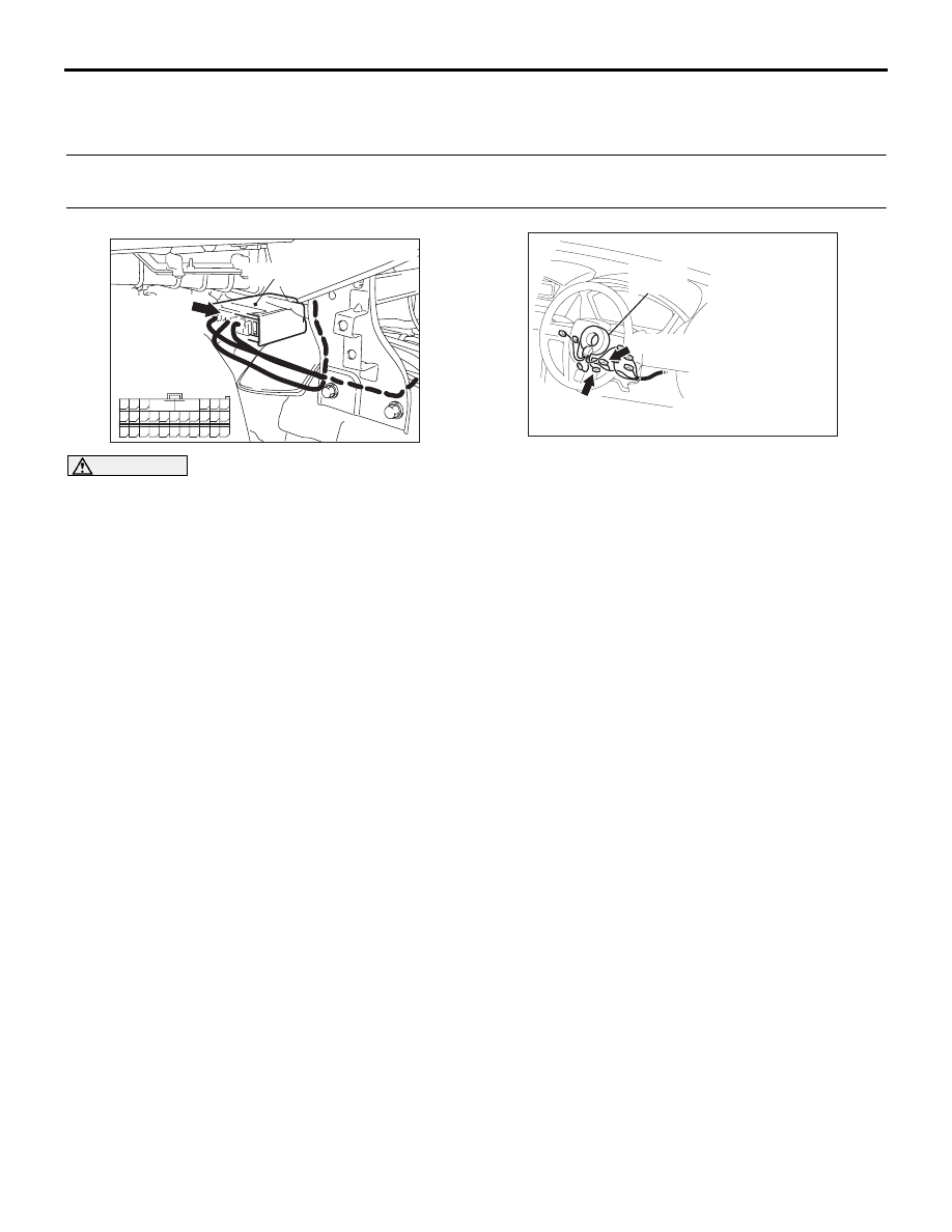
24DB062A
CONNECTOR: C-121
C-121 (Y)
SRS-ECU
42
31
38
27
21
41
28
39
22
30
25
47
36
33
44
34
45
37
48
26
29
23
40
32
43
35
46
24
B
A
C-121
INSTRUMENT
HARNESS
CONNECTOR
(REAR VIEW)
52DB006A
C-307 (Y)
CONNECTORS: C-305, C-307
CLOCK
SPRING
C-305 (Y)