Mitsubishi 380. Manual - part 768


  Index      Mitsubishi     Mitsubishi 380 - service repair manual 2005 year


Search            


Content   ..  766  767  768  769   ..


Mitsubishi 380. Manual - part 768


FUEL TANK

FUEL SUPPLY

13B-12

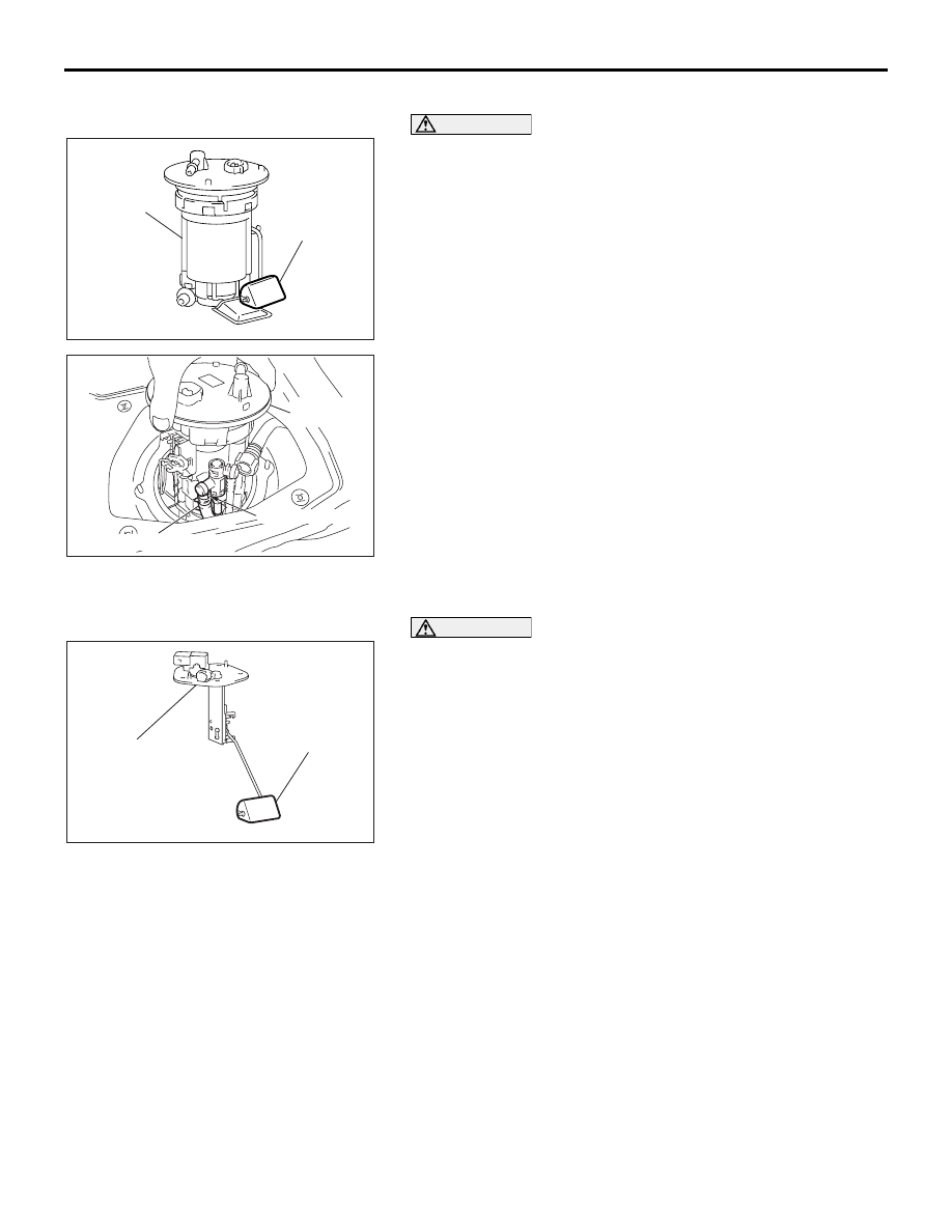
<<E>> FUEL PUMP MODULE REMOVAL

CAUTION

When withdrawing the fuel pump module from the fuel 
tank, be careful not to damage the module unit and the 
float.

Make alignment marks between the suction hose and the fuel 
pump module and then disconnect the suction hose to remove 
the fuel pump module.

.

<<F>> FUEL LEVEL SENSOR (SUB) REMOVAL

CAUTION

When withdrawing the fuel level sensor (sub) from the fuel 
tank, be careful not to damage the sensor unit and the 
float.
1.Remove the fuel level sensor (sub) mounting bolts and 
remove the fuel tank gauge unit from the tank hole.

AC307207

FUEL PUMP 
MODULE

FLOAT

AB

AC306092AB

SUCTION HOSE

FUEL PUMP 
MODULE

MATING MARKS

AC307206AB

FLOAT

FUEL LEVEL 
SENSOR (SUB)

FUEL TANK

FUEL SUPPLY

13B-13

INSTALLATION SERVICE POINTS

.

>>A<< FUEL LEVEL SENSOR (SUB) INSTALLA-
TION

CAUTION

When inserting the fuel level sensor (sub) into the fuel 
tank, be careful not to damage the sensor unit and the 
float.
1. Install the fuel level sensor to the fuel tank hole. 

.

>>B<< FUEL PUMP MODULE INSTALLATION

CAUTION

When installing the fuel pump module into the fuel tank, be 
careful not to damage the module unit and the float.

1. Align the mark of the suction hose with that of the fuel pump 

module, and then connect the suction hose to the fuel pump 
module.

2. Install the fuel pump module into the fuel tank while ensuring 

that the suction hose is not kinked.

.

AC307206AB

FLOAT

FUEL LEVEL 
SENSOR (SUB)

AC307207

FUEL PUMP 
MODULE

FLOAT

AB

AC306092AB

SUCTION HOSE

FUEL PUMP 
MODULE

MATING MARKS

FUEL TANK

FUEL SUPPLY

13B-14

>>C<< FUEL HIGH-PRESSURE HOSE/FUEL 
HIGH-PRESSURE HOSE CONNECTION 
INSTALLATION

CAUTION

Connect the fuel high-pressure hose, and then pull it gen-
tly in the direction of removal to check that the hose is 
firmly connected.
Apply clean engine oil to the tips of the main pipe nozzle and 
the fuel main pipe, and connect connector of the fuel high-pres-
sure hose to them.

.

>>D<< FUEL TANK BAND/FUEL TANK ASSEMBLY 
INSTALLATION

1. Raise the fuel tank assembly carefully with a transaxle jack.

2. Ensure that the fuel tank assembly does not interfere with 

surrounding parts. Then install the fuel tank band and 
tighten the mounting nuts to the specified torque.

Tightening torque: 26 

± 4 Nm (19 ± 3 ft-lb)

3. Again, ensure that the fuel tank assembly does not interfere 

with surrounding components. If the fuel tank assembly 
interferes surrounding components, remove the fuel tank 
assembly and the tank band and reinstall them.

INSPECTION

M1135002000241

.

FUEL SHUT-OFF VALVE CHECK

Check that the flapper of the fuel shut-off valve opens and 
closes as shown in the illustration.

AC209221

CONNECTOR

MAIN PIPE NOZZLE OR
FUEL MAIN PIPE

AB

AC005004A

CLOSED

OPEN

FLAPPER

80°

03DB148A

SPECIFICATIONS

FUEL SUPPLY

13B-15

SPECIFICATIONS

FASTENER TIGHTENING SPECIFICATIONS

M1135003900322

SERVICE SPECIFICATION

M1135000300257

ITEM

SPECIFICATIONS

Fuel tank band nut

26 

± 4 N⋅m (19 ± 3 ft-lb)

Hole cover screw

1.5 

± 0.5 N⋅m (14 ± 4 in-lb)

ITEM

STANDARD VALUE


Content   ..  766  767  768  769   ..