Mitsubishi 380. Manual - part 728


  Index      Mitsubishi     Mitsubishi 380 - service repair manual 2005 year


Search            


Content   ..  726  727  728  729   ..


Mitsubishi 380. Manual - part 728


DIAGNOSIS

CONTROLLER AREA NETWORK (CAN)

54C-323

DIAGNOSTIC ITEM 8: Diagnose CAN bus lines thoroughly

NOTE: When diagnosing CAN-BUS on vehicles 
with manual transmission (M/T), disregard 
A/T-ECU and it’s wiring circuits and measure 
between ABS-ECU and ENGINE-ECU only.

NOTE: When diagnosing CAN-BUS on vehicles 
not equipped with a multi-centre display, disre-
gard the multi-centre display and it’s wiring cir-
cuits.

CAUTION

When servicing a CAN bus line, ground yourself 
by touching a metal object such as an unpainted 
water pipe. If you fail to do so, a component con-
nected to the CAN bus line may be damaged.

.

16DB402A

A-02 (GR)

CONNECTOR: A-02 

A-02 HARNESS CONNECTOR:

16DB407A

COVER

ENGINE

CONTROL

UNIT

AIR

CLEANER

A/T

CONTROL

UNIT

16DB474A

C-218 (GR)

CONNECTOR: C-218

HARNESS SIDE

JUNCTION BLOCK

(REAR VIEW)

16DB472A

C-101

C-125 (B)

C-29

C-02

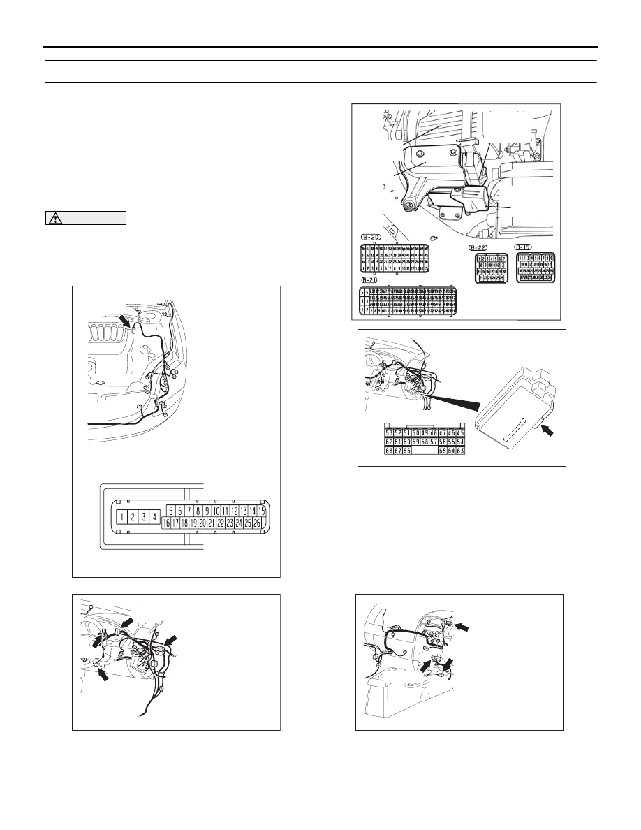
CONNECTORS: C-02, C-29, C-101, C-125

16DB489A

CONNECTORS: C-05, C-15, C-121

C-121 (Y)

C-15 (B)

C-05 (B)

DIAGNOSIS

CONTROLLER AREA NETWORK (CAN)

54C-324

TROUBLE JUDGMENT

If the MUT-III cannot received signals from ECUs, 
CAN bus line connector(s) are broken or an open cir-
cuit has occurred.

.

COMMENTS ON TROUBLE SYMPTOM

The wiring harness wire or connectors may have 
loose, corroded, or damage terminals, or terminals 
pushed back in the connector, or an ECU may be 
defective.

.

TROUBLESHOOTING HINTS

• Refer to circuit diagrams GROUP-

90

• Refer to configuration diagrams GROUP-

80

• The wiring harness or connectors may have 

loose, corroded, or damage terminals, or termi-
nals pushed back in the connector

• The ETACS-ECU may be defective

• The combination meter may be defective

• The A/C-ECU may be defective

• The SRS-ECU may be defective

• The multi-center display unit  may be defective

• The ABS-ECU may be defective

• The A/T-ECU may be defective

• The ENGINE-ECU may be defective

NOTE: When diagnosing CAN-BUS on vehi-

cles with manual transmission (M/T), disregard 
A/T-ECU and it’s wiring circuits and measure 
between ABS-ECU and ENGINE-ECU only.

NOTE: When diagnosing CAN-BUS on vehicles 
not equipped with a multi-centre display, disre-
gard the multi-centre display and it’s wiring cir-
cuits.

DIAGNOSIS

CONTROLLER AREA NETWORK (CAN)

54C-325

DIAGNOSIS

Required Special Tools:

• MB991223: Harness Set

• MB991958: Diagnostic Tool (MUT-III Sub Assembly)

• MB991824: Vehicle Communication Interface (V.C.I.)

• MB991827: MUT-III USB Cable

• MB991910: MUT-III Main Harness A

• MB991219: Inspection Test Harness

• MB992045: A/T-ECU Check Harness

• MB992044: ENGINE-ECU Check Harness

STEP 1. Check data link connector C-125 for loose, 
corroded or damaged terminals, or terminals pushed back 
in the connector.

CAUTION

The strand end of the twisted wire should be within 10 cm 
(4 inches) from the connector. For details refer to 

P.54C-4

.

Q: Is data link connector C-125 in good condition?

YES : Go to Step 2.
NO :  Repair the damaged parts.

16DB501A

CONNECTOR: C-125

C-125 (B)

DIAGNOSIS

CONTROLLER AREA NETWORK (CAN)

54C-326

STEP 2. Check the CAN bus lines at the data link 
connector. Measure the resistance at the data link 
connector C-125.

CAUTION

A digital multimeter should be used. For details refer to 

P.54C-4

.

CAUTION

The test wiring harness should be used. For details refer to 

P.54C-4

.

(1) Measure the resistance at the data link connector.
(2) Turn the ignition switch to the "LOCK" (OFF) position.

CAUTION

Disconnect the negative battery terminal. For details refer 
to 

P.54C-4

.

(3) Disconnect the negative battery terminal.

(4) Measure the resistance between data link connector 

terminals 6 and 14.

Q: How much resistance is measured?

2 ohms or less : Diagnostic Item 5: Check the CAN_L and 

H lines for a short circuit. Refer to 

P.54C-239

No continuity : Diagnostic Item 6: Diagnose terminator 

resistors at both ends. Refer to 

P.54C-273

More than 2 ohms but continuity exists : Go to Step 3.

16DB501A

CONNECTOR: C-125

C-125 (B)

AC204740

AC204740

AC204740

AC204740

AC204740

AC204740

AC204740

AC204740

AC204740DA

TEST 
HARNESS

TEST 
HARNESS

HARNESS SIDE: C-125


Content   ..  726  727  728  729   ..