Mitsubishi 380. Manual - part 714


  Index      Mitsubishi     Mitsubishi 380 - service repair manual 2005 year


Search            


Content   ..  712  713  714  715   ..


Mitsubishi 380. Manual - part 714


DIAGNOSIS

CONTROLLER AREA NETWORK (CAN)

54C-266

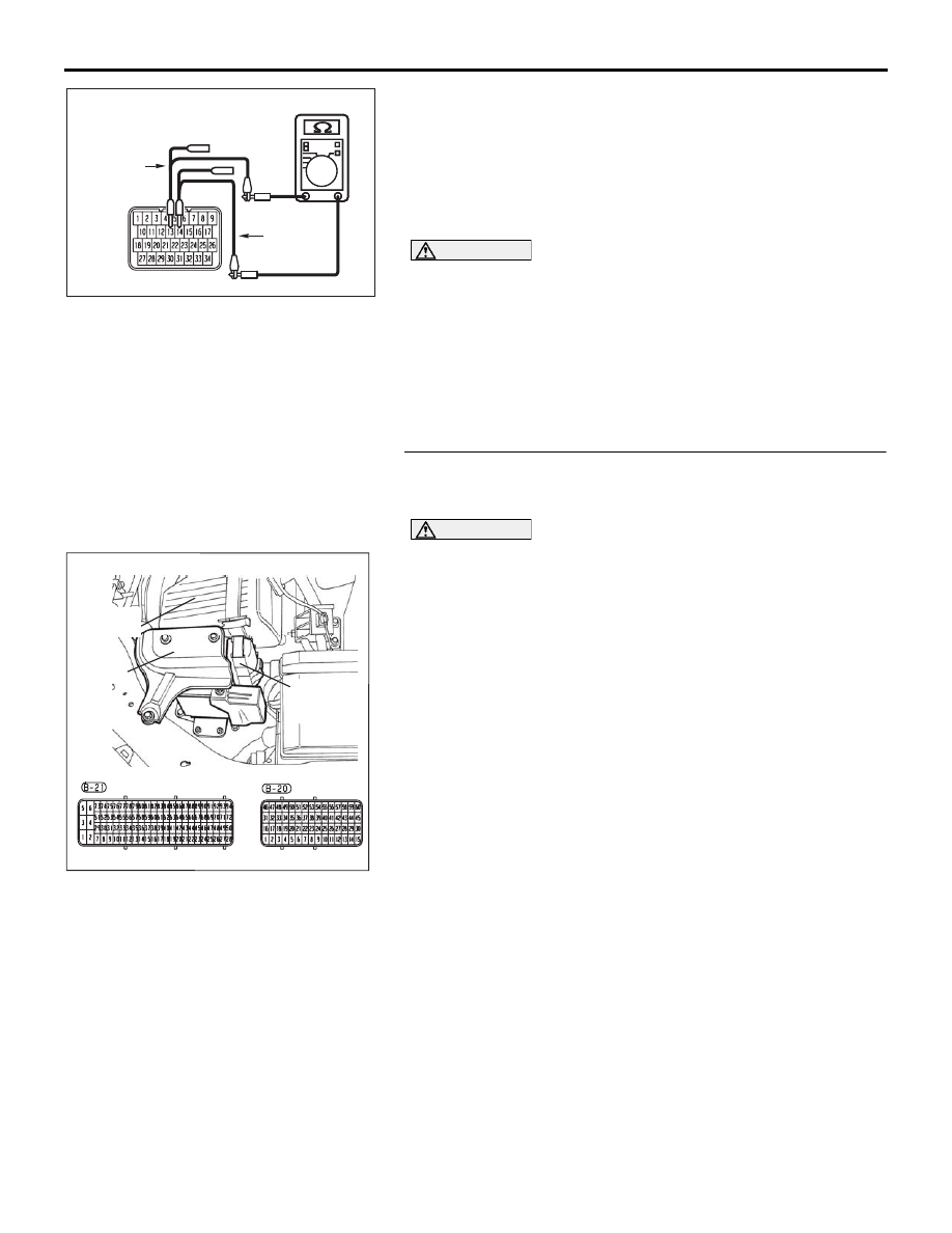
(4) Measure the resistance between A/T- ECU connector 

terminals 13 and 14.

OK: 1 k

 or more

NOTE: When diagnosing CAN-BUS on vehicles with 
manual transmission (M/T), disregard A/T-ECU and it’s wir-
ing circuits and measure between ABS-ECU and 
ENGINE-ECU only.

CAUTION

Strictly observe the specified wiring harness repair proce-
dure. For details refer to 

P.54C-5

.

Q: Does the resistance measure 1 k

 or more?

YES : If the resistance measures 1 k

Ω or more, go to Step 

31  .

NO :  If the resistance measures less than 1 k

Ω, repair the 

wiring harness between A/T- ECU connector and 
ABS-ECU connector.

STEP 31. Check ENGINE- ECU connector B-21 for loose, 
corroded or damaged terminals, or terminals pushed back 
in the connector.

CAUTION

The strand end of the twisted wire should be within 10 cm 
(4 inches) from the connector. For details refer to 

P.54C-4

.

Q: Is ENGINE- ECU connector B-21 in good condition?

YES : Go to Step 32.
NO :  Repair the damaged parts.

16DB502A

HARNESS SIDE: B-19

TEST
HARNESS

TEST
HARNESS

16DB400A

COVER

ENGINE

CONTROL

UNIT

AIR

CLEANER

DIAGNOSIS

CONTROLLER AREA NETWORK (CAN)

54C-267

STEP 32. Check the CAN_L and H lines (communication 
lines only) between the ENGINE- ECU connector and the 
A/T-ECU connector for a short circuit. Measure the 
resistance at ENGINE- ECU connector B-21.

NOTE: When diagnosing CAN-BUS on vehicles with 
manual transmission (M/T), disregard A/T-ECU and it’s wir-
ing circuits and measure between ABS-ECU and 
ENGINE-ECU only.

CAUTION

A digital multimeter should be used. For details refer to 

P.54C-4

.

CAUTION

The test wiring harness should be used. For details refer to 

P.54C-4

.

(1) Disconnect ENGINE- ECU connector B-21 and A/T-ECU 

connector B-19, and measure the resistance at the harness 
side of ENGINE- ECU connector B-21.

(2) Turn the ignition switch to the "LOCK" (OFF) position.

CAUTION

Disconnect the negative battery terminal. For details refer 
to 

P.54C-4

.

(3) Disconnect the negative battery terminal.

NOTE: When diagnosing CAN-BUS on vehicles with 
manual transmission (M/T), disregard A/T-ECU and it’s wir-
ing circuits and measure between ABS-ECU and 
ENGINE-ECU only.

16DB480A

COVER

ENGINE

CONTROL

UNIT

AIR

CLEANER

A/T

CONTROL

UNIT

16DB400A

COVER

ENGINE

CONTROL

UNIT

AIR

CLEANER

DIAGNOSIS

CONTROLLER AREA NETWORK (CAN)

54C-268

(4) Measure the resistance between ENGINE- ECU connector 

terminals 64 and 86.

OK: 1 k

 or more

NOTE: When diagnosing CAN-BUS on vehicles with 
manual transmission (M/T), disregard A/T-ECU and it’s wir-
ing circuits and measure between ABS-ECU and 
ENGINE-ECU only.

CAUTION

Strictly observe the specified wiring harness repair proce-
dure. For details refer to 

P.54C-5

.

Q: Does the resistance measure 1 k

 or more?

YES : If the resistance measures 1 k

Ω or more, go to Step 

33  .

NO :  If the resistance measures less than 1 k

Ω, repair the 

wiring harness between ENGINE- ECU connector 
and A/T-ECU connector.

16DB503A

HARNESS SIDE: B-21

TEST 
HARNESS

TEST 
HARNESS

DIAGNOSIS

CONTROLLER AREA NETWORK (CAN)

54C-269

STEP 33. Check the ABS-ECU for short circuit. Measure 
the resistance at ABS-ECU connector A-02.

CAUTION

A digital multimeter should be used. For details refer to 

P.54C-4

.

(1) Disconnect ABS-ECU connector A-02, and measure the 

resistance at the component side of ABS-ECU connector 
A-02.

(2) Measure the resistance between ABS-ECU connector 

terminals 14 and 25.

OK: 1 k

 or more

Q: Does the resistance measure 1 k

 or more?

YES : If the resistance measures 1 k

Ω or more, go to Step 

34  .

NO :  If the resistance measures less than 1 k

Ω, replace the 

ABS-ECU.

16DB402A

A-02 (GR)

CONNECTOR: A-02 

A-02 HARNESS CONNECTOR:

16DB504A

COMPONENT SIDE: A-02

TEST 
HARNESS

TEST 

HARNESS


Content   ..  712  713  714  715   ..