Mitsubishi 380. Manual - part 693


  Index      Mitsubishi     Mitsubishi 380 - service repair manual 2005 year


Search            


Content   ..  691  692  693  694   ..


Mitsubishi 380. Manual - part 693


DIAGNOSIS

CONTROLLER AREA NETWORK (CAN)

54C-182

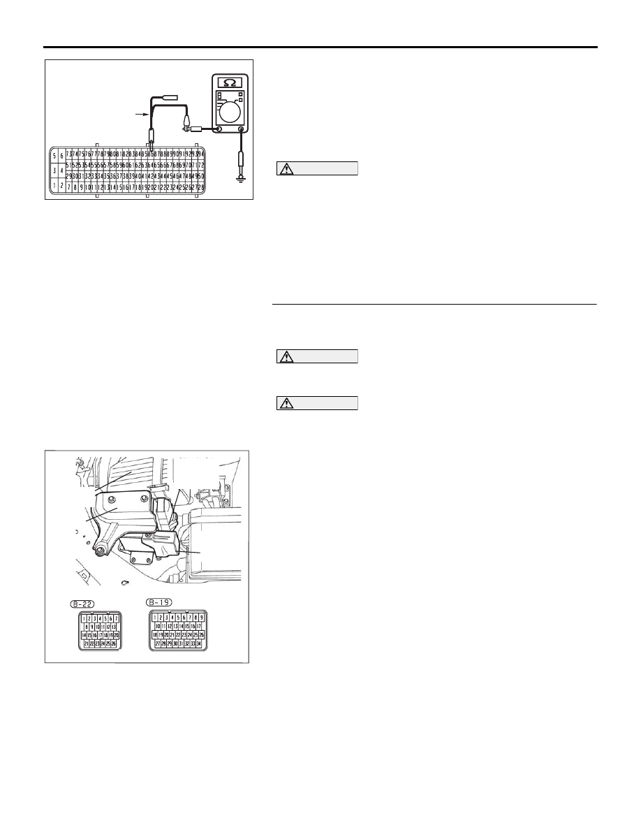
(4) Measure the resistance between ENGINE- ECU connector 

terminal 86 and body ground.

OK: 1 k

 or more

NOTE: When diagnosing CAN BUS on vehicles with 

manual transmission (M/T) disregard A/T-ECU and it’s wir-
ing circuits and measure between ABS-ECU and 
ENGINE-ECU only.

CAUTION

Strictly observe the specified wiring harness repair proce-
dure. For details refer to 

P.54C-5

.

Q: Does the resistance measure 1 k

 or more?

YES : If the resistance measures 1 k

Ω or more, go to Step 

47   .

NO :  If the resistance measures less than 1 k

Ω, repair the 

wiring harness between ENGINE- ECU connector 
and A/T-ECU connector.

STEP 47. Check the CAN_L line inside the A/T-ECU for 
short to ground. Measure the resistance at A/T-ECU 
connector B-19.

CAUTION

A digital multimeter should be used. For details refer to 

P.54C-4

.

CAUTION

The test wiring harness should be used. For details refer to 

P.54C-4

.

(1) Disconnect A/T-ECU connector B-19.

NOTE: When diagnosing CAN BUS on vehicles with 

manual transmission (M/T) disregard A/T-ECU and it’s wir-
ing circuits and measure between ABS-ECU and 
ENGINE-ECU only.

16DB497A

HARNESS SIDE: B-21

TEST
HARNESS

16DB480A

COVER

ENGINE

CONTROL

UNIT

AIR

CLEANER

A/T

CONTROL

UNIT

DIAGNOSIS

CONTROLLER AREA NETWORK (CAN)

54C-183

(2) Connect special tool MB992045 (A/T check harness) to the 

A/T-ECU and the wiring harness, and measure the 
resistance at special tool MB992045 (A/T check harness).

(3) Turn the ignition switch to the "LOCK" (OFF) position.

NOTE: When diagnosing CAN BUS on vehicles with 

manual transmission (M/T) disregard A/T-ECU and it’s wir-
ing circuits and measure between ABS-ECU and 
ENGINE-ECU only.

CAUTION

Disconnect the negative battery terminal. For details refer 
to 

P.54C-4

.

(4) Disconnect the negative battery terminal.
(5) Measure the resistance between special tool MB992045 

(A/T check harness) connector terminal 14 and body 
ground.

OK: 1 k

 or more

Q: Does the resistance measure 1 k

 or more?

YES : If the resistance measures 1 k

Ω or more, diagnose 

CAN bus lines thoroughly by referring to 

P.54C-323

.

NO :  If the resistance measures less than 1 k

Ω, replace the 

A/T-ECU.

16DB498A

TEST
HARNESS

SPECIAL TOOL

MB992045

A/T-

ECU

MEASURE AT THIS CONNECTOR

SPECIAL TOOL MB992045 

CONNECTOR

DIAGNOSIS

CONTROLLER AREA NETWORK (CAN)

54C-184

DIAGNOSTIC ITEM 4: Diagnose shorts in the ground to CAN bus line <Vehicles with multi-center 
display >

NOTE: When diagnosing CAN-BUS on vehicles 
with manual transmission (M/T), disregard 
A/T-ECU and it’s wiring circuits.

NOTE: When diagnosing CAN-BUS on vehicles 
that are not equipped with a multi-centre display, 
disregard the multi-centre display and it’s wiring 
circuits.

CAUTION

When servicing a CAN bus line, ground yourself 
by touching a metal object such as an unpainted 
water pipe. If you fail to do so, a component con-
nected to the CAN bus line may be damaged.

16DB402A

A-02 (GR)

CONNECTOR: A-02 

A-02 HARNESS CONNECTOR:

16DB407A

COVER

ENGINE

CONTROL

UNIT

AIR

CLEANER

A/T

CONTROL

UNIT

16DB489A

CONNECTORS: C-05, C-15, C-121

C-121 (Y)

C-15 (B)

C-05 (B)

16DB472A

C-101

C-125 (B)

C-29

C-02

CONNECTORS: C-02, C-29, C-101, C-125

DIAGNOSIS

CONTROLLER AREA NETWORK (CAN)

54C-185

.

TROUBLE JUDGMENT

A short to ground may be present when the voltage 
between the CAN bus line (CAN_L or CAN_H) and 
body ground is less than 1.0 V. In this condition, an 
abnormal voltage may be measured at CAN_L and 
CAN_H lines.

.

COMMENTS ON TROUBLE SYMPTOM

The wiring harness wire or connectors may have 
loose, corroded, or damage terminals, or terminals 
pushed back in the connector, or an ECU may be 
defective.

.

TROUBLESHOOTING HINTS

• Refer to circuit diagrams GROUP-

90

• Refer to configuration diagrams GROUP-

80

• The wiring harness or connectors may have 

loose, corroded, or damaged terminals, or termi-
nals pushed back in the connector

• The ETACS-ECU may be defective

• The combination meter may be defective

• The A/C-ECU may be defective

• The multi-centre display unit  may be defective

• The SRS-ECU may be defective

• The ABS-ECU may be defective

• The A/T- ECU may be defective

• The ENGINE- ECU may be defective

NOTE: When diagnosing CAN-BUS on vehi-

cles with manual transmission (M/T), disregard 
A/T-ECU and it’s wiring circuits.

NOTE: When diagnosing CAN-BUS on vehicles 
that are not equipped with a multi-centre display, 
disregard the multi-centre display and it’s wiring 
circuits.

16DB474A

C-218 (GR)

CONNECTOR: C-218

HARNESS SIDE

JUNCTION BLOCK

(REAR VIEW)


Content   ..  691  692  693  694   ..