Mitsubishi 380. Manual - part 682
DIAGNOSIS
CONTROLLER AREA NETWORK (CAN)
54C-138
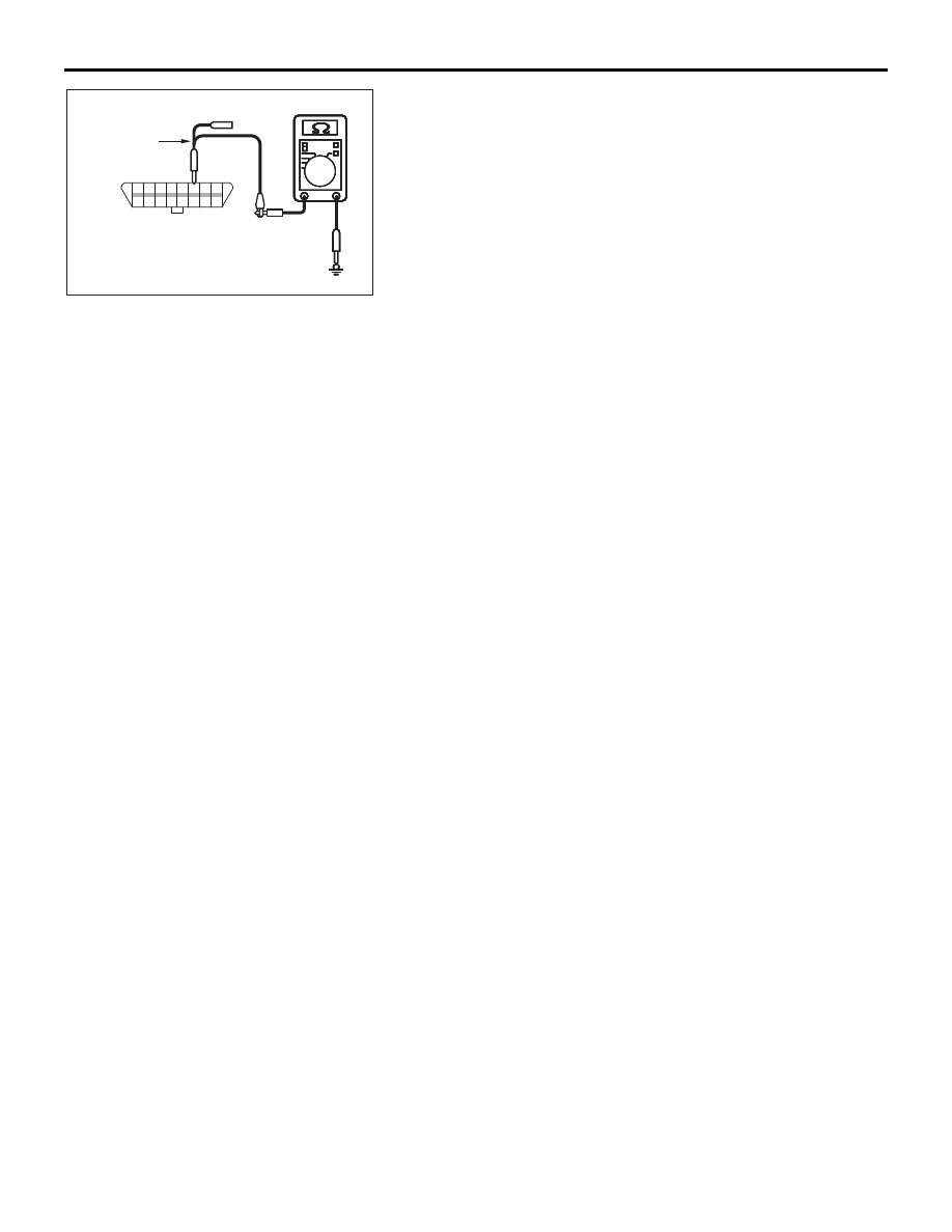
(4) Measure the resistance between data link connector
terminal 6 and body ground.
OK: 1 k
Ω or more
Q: Does the resistance measure 1 k
Ω or more?
YES : If the resistance measures 1 k
Ω or more, go to Step 3
.
NO : If the resistance measures less than 1 k
Ω, go to Step
AC209364
Y
8
16
15
7
5
1314
6
12
4
2
1011
3
9
1
AC209364
AC209364
AC209364
AC209364
AC209364HT
HARNESS SIDE: C-125
TEST
HARNESS