Mitsubishi 380. Manual - part 679


  Index      Mitsubishi     Mitsubishi 380 - service repair manual 2005 year


Search            


Content   ..  677  678  679  680   ..


Mitsubishi 380. Manual - part 679


DIAGNOSIS

CONTROLLER AREA NETWORK (CAN)

54C-127

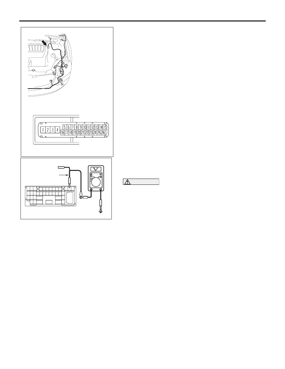
(1) Disconnect intermediate connector C-29 and ABS-ECU 

connector A-02, and measure the voltage at the male side 
of intermediate connector C-29 (at front wiring harness 
side).

(2) Turn the ignition switch to the "ON" position.

(3) Measure the voltage between intermediate connector 

terminal 12 and body ground.

OK: 1.0 V or less

CAUTION

Strictly observe the specified wiring harness repair proce-
dure. For details refer to 

P.54C-5

.

Q: Does the voltage measure 1.0 V or less?

YES : If the voltage measures 1.0 V or less, go to Step 50.
NO :  If the voltage measures more than 1.0 V, repair the 

wiring harness between intermediate connector C-29 
and ABS-ECU connector.

16DB402A

A-02 (GR)

CONNECTOR: A-02 

A-02 HARNESS CONNECTOR:

AC209365

2 3

27

32

28

33

16

15

4 5

19

18

29

17

34

7 8

35

22

21

9 10

30

36

31

37

25

24

23

6

20

1

14

26

11

13

12

38

AC209365

MALE SIDE: C-29

TEST HARNESS

GA

DIAGNOSIS

CONTROLLER AREA NETWORK (CAN)

54C-128

STEP 50. Check the CAN_L line (communication line only) 

between the A/T-ECU connector and ABS-ECU connector 

for a short to the power supply. Measure voltage at 

A/T-ECU connector B-19.

• Refer to circuit diagrams GROUP-

90

• Refer to configuration diagrams GROUP-

80

NOTE: When diagnosing CAN BUS on vehicles with 
manual transmission (M/T) please disregard A/T ECU and 
its circuits.

CAUTION

A digital multimeter should be used. For details refer to 

P.54C-4

.

CAUTION

The test wiring harness should be used. For details refer to 

P.54C-4

.

DIAGNOSIS

CONTROLLER AREA NETWORK (CAN)

54C-129

(1) Disconnect A/T-ECU connector B-19 and ABS-ECU 

connector A-02, and measure the voltage at the harness 
side of A/T-ECU connector B-19.

(2) Turn the ignition switch to the "ON" position.
NOTE: When diagnosing CAN BUS on vehicles with 
manual transmission (M/T) please disregard A/T ECU and 
its circuits.

16DB402A

A-02 (GR)

CONNECTOR: A-02 

A-02 HARNESS CONNECTOR:

16DB480A

COVER

ENGINE
CONTROL
UNIT

AIR
CLEANER

A/T
CONTROL
UNIT

DIAGNOSIS

CONTROLLER AREA NETWORK (CAN)

54C-130

(3) Measure the voltage between A/T-ECU connector terminal 

14 and body ground.

OK: 1.0 V or less

CAUTION

Strictly observe the specified wiring harness repair proce-
dure. For details refer to 

P.54C-5

.

Q: Does the voltage measure 1.0 V or less?

YES : If the voltage measures 1.0 V or less, go to Step 51.
NO :  If the voltage measures more than 1.0 V, repair the 

wiring harness between ENGINE-ECU connector and 
ABS-ECU connector.

STEP 51. Check the CAN_L line inside the ABS-ECU for a 
short to the power supply. Measure the voltage at 
ABS-ECU connector A-02 for loose, corroded or damaged 
terminals, or terminals pushed back in the connector.

• Refer to circuit diagrams GROUP-

90

• Refer to configuration diagrams GROUP-

80

CAUTION

A digital multimeter should be used. For details refer to 

P.54C-4

.

CAUTION

The test wiring harness should be used. For details refer to 

P.54C-4

.

(1) Disconnect ABS-ECU connector A-02.

16DB485A

 B-19

TEST
HARNESS

16DB402A

A-02 (GR)

CONNECTOR: A-02 

A-02 HARNESS CONNECTOR:


Content   ..  677  678  679  680   ..