Mitsubishi 380. Manual - part 651
DIAGNOSIS
CONTROLLER AREA NETWORK (CAN)
54C-15
DIAGNOSIS
CAN BUS DIAGNOSTICS TABLE
M1548300200055
This diagnosis applies only to the CAN bus lines. If a
different system is defective, proceed to the applica-
ble diagnosis section for each system. Observe the
diagnosis procedure below only when the CAN bus
line is defective.
CAUTION
During diagnosis, a DTC code associated with
another system may be set when the ignition
switch is turned on with connector(s) discon-
nected. After completing the repair, confirm all
systems for DTC code(s). If DTC code(s) are set,
erase them all.
NOTE: all screens below appear with vehicles incor-
porating automatic transmisssion ECU, therefore
when diagnosing can bus on vehicles with manual
transmission (M/T), the A/T ECU will not be dis-
played on screens.
Vehicles without multi-center display
MUT-III SCREEN
DIAGNOSIS DETAILS
REFERENCE
PAGE
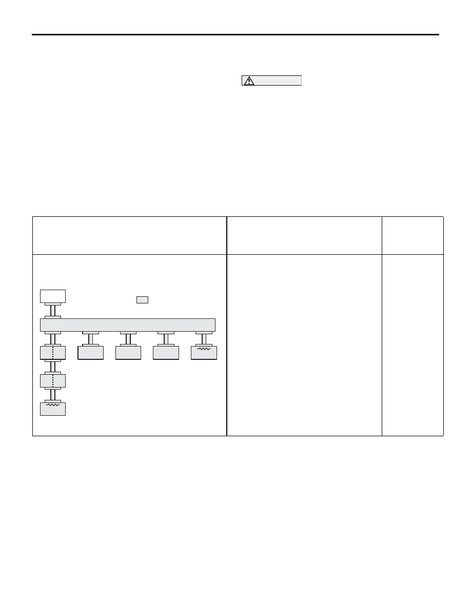
<Comment>
Short circuit to battery in red displayed area is
estimated.
Diagnostic Item 1
Diagnose shorts in the power supply to
CAN bus line <Vehicles without
multi-center display >
16DB367A
ETACS
-ECU
AC-ECU
: Red section on screen
ENGINE
-ECU
SRS-ECU
METER
-ECU
ABS-ECU
MUT
J/C
A/T-ECU