Mitsubishi 380. Manual - part 537


  Index      Mitsubishi     Mitsubishi 380 - service repair manual 2005 year


Search            


Content   ..  535  536  537  538   ..


Mitsubishi 380. Manual - part 537


MULTIPORT FUEL INJECTION (MPI) DIAGNOSIS

MULTIPORT FUEL INJECTION (MPI)

13A-240

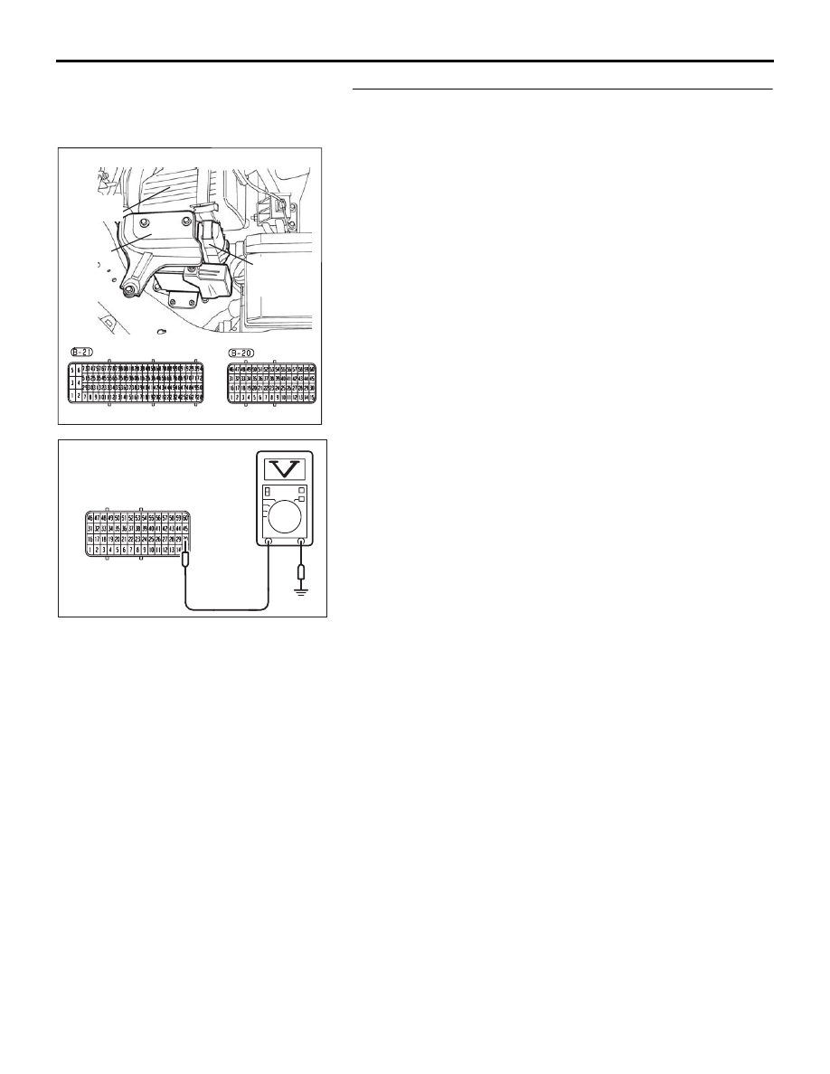
STEP 2. Measure the sensor output voltage at 
ENGINE-ECU connector B-20 by using  ENGINE-ECU 
check harness special tool MB992044.
(1) Disconnect the all ENGINE-ECU connectors and connect  

ENGINE-ECU check harness special tool MB992044 
between the separated connectors.

(2) Start the engine and run at idle.
(3) Ensure engine is at running temperature (80

° C or higher).

(4) Measure the voltage between terminal No. 30 and ground.

• Warm engine. When the engine is revved, the output 

voltage should alternate between 0 and 0.6-1.0 volts.

(5) Turn the ignition switch to the "LOCK" (OFF) position.

Q: Is the measured voltage cycling within the specified 

range?
YES : 
Go to Step 6.
NO :  Then go to Step 3.

16DB400A

COVER

ENGINE

CONTROL

UNIT

AIR

CLEANER

03DB213A

B-20 HARNESS 

CONNECTOR 

MULTIPORT FUEL INJECTION (MPI) DIAGNOSIS

MULTIPORT FUEL INJECTION (MPI)

13A-241

STEP 3. Check harness connector B-24 at left bank heated 
oxygen sensor (rear) and harness connector B-20 at 
ENGINE-ECU for damage.
Q: Is the harness connector in good condition?

YES : Go to Step 4.
NO :  Repair or replace it. Refer to GROUP 00E, Harness 

Connector Inspection 

P.00E-2

. Then go to Step 6. 

1

2

3

4

AK303079

HARNESS

CONNECTOR:

COMPONENT SIDE

CONNECTOR: B-24

AB

LEFT BANK

HEATED OXYGEN

SENSOR (REAR)

B-24 (GR)

16DB400A

COVER

ENGINE

CONTROL

UNIT

AIR

CLEANER

MULTIPORT FUEL INJECTION (MPI) DIAGNOSIS

MULTIPORT FUEL INJECTION (MPI)

13A-242

STEP 4. Check for short to heater circuit ground harness 
wire between left bank heated oxygen sensor (rear) 
connector B-24 (terminal No. 1) and ENGINE-ECU 
connector B-20 (terminal No. 30).
Q: Is the harness wire in good condition?

YES : Go to Step 5.
NO :  Repair or replace it. Then go to Step 6.

1

2

3

4

AK303079

HARNESS

CONNECTOR:

COMPONENT SIDE

CONNECTOR: B-24

AB

LEFT BANK

HEATED OXYGEN

SENSOR (REAR)

B-24 (GR)

16DB400A

COVER

ENGINE

CONTROL

UNIT

AIR

CLEANER

MULTIPORT FUEL INJECTION (MPI) DIAGNOSIS

MULTIPORT FUEL INJECTION (MPI)

13A-243

STEP 5. Using diagnostic tool, check data list item AF: 
Heated Oxygen Sensor Bank 2, Sensor 2 (left rear).

CAUTION

To prevent damage to diagnostic tool, always turn the igni-
tion switch to the "LOCK" (OFF) position before connect-
ing or disconnecting diagnostic tool .
(1) Connect diagnostic tool  to the data link connector.
(2) Start the engine and run at idle.
(3) Set diagnostic tool  to the data reading mode for item AF, 

Heated Oxygen Sensor Bank 2, Sensor 2 (left rear).

• Warming up the engine. When the engine is revved, the 

output voltage should alternate between 0 and 0.6 to 1.0 
volts.

(4) Turn the ignition switch to the "LOCK" (OFF) position.

Q: Is the sensor operating properly?

YES : It can be assumed that this malfunction is intermittent. 

Refer to GROUP 00, How to Use 
Troubleshooting/Inspection Service Points 

− How to 

Cope with Intermittent Malfunctions 

P.00-14

.

NO :  Replace the sensor. Then go to Step 6.

STEP 6. Test the EOBD drive cycle.
(1) Carry out a test drive with the drive cycle pattern. Refer to 

Diagnostic Function 

− EOBD Drive Cycle − 

P.13A-11

.

(2) Check the diagnostic trouble code (DTC).

Q: Is DTC P0156 set?

YES : Retry the troubleshooting.
NO :  The inspection is complete.

00DB076A

MB991910

DATA LINK

CONNECTOR

MB991824

MB991827


Content   ..  535  536  537  538   ..