Mitsubishi 380. Manual - part 490


  Index      Mitsubishi     Mitsubishi 380 - service repair manual 2005 year


Search            


Content   ..  488  489  490  491   ..


Mitsubishi 380. Manual - part 490


MULTIPOINT FUEL INJECTION (MPI) DIAGNOSIS

MULTIPOINT FUEL INJECTION (MPI)

13A-52

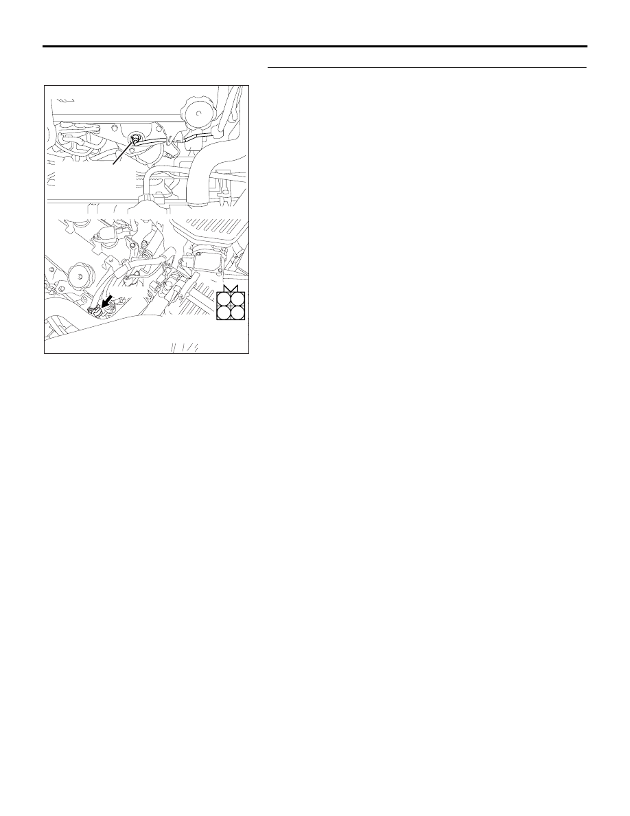
STEP 2. Check the left bank heated oxygen sensor (front).
(1) Disconnect left bank heated oxygen sensor (front) 

connector B-25.

(2) Measure the resistance between heated oxygen sensor 

connector terminal No. 3 and terminal No. 4.

Standard value: 9.0 

 11.0 ohms [at 20°C (68°F)]

Q: Is the measured resistance between 9.0 and 11.0 ohms 

[at 20

°C (68°F)]?

YES : Go to Step 3.
NO :  Replace the left bank heated oxygen sensor (front). 

Then go to Step 11.

AK303071

1

2

3

4

LEFT BANK

HEATED OXYGEN

SENSOR (FRONT)

CONNECTOR: B-25

B-25 (B)

AB

HARNESS

CONNECTOR:

COMPONENT SIDE

MULTIPOINT FUEL INJECTION (MPI) DIAGNOSIS

MULTIPOINT FUEL INJECTION (MPI)

13A-53

STEP 3. Measure the power supply voltage at left bank 
heated oxygen sensor (front) harness side connector B-25.
(1) Disconnect the connector B-25 and measure at the harness 

side.

(2) Turn the ignition switch to the "ON" position.

(3) Measure the voltage between terminal No. 3 and ground.

• Voltage should be battery positive voltage.

(4) Turn the ignition switch to the "LOCK" (OFF) position.

Q: Is battery positive voltage (approximately 12 volts) 

present?
YES : 
Go to Step 5.
NO :  Go to Step 4.

AK303071

1

2

3

4

LEFT BANK

HEATED OXYGEN

SENSOR (FRONT)

CONNECTOR: B-25

B-25 (B)

AB

HARNESS

CONNECTOR:

COMPONENT SIDE

03DB210A

B-25 HARNESS 

CONNECTOR: 

COMPONENT SIDE

1

2

3

4

MULTIPOINT FUEL INJECTION (MPI) DIAGNOSIS

MULTIPOINT FUEL INJECTION (MPI)

13A-54

STEP 4. Check harness connector B-17X at the MPI relay 
for damage.
Q: Is the harness connector in good condition?

YES : Repair harness wire between MPI relay connector 

B-17X (terminal No. 4) and left bank heated oxygen 
sensor (front) connector B-25 (terminal No. 3) 
because of open circuit or short circuit to ground. 
Then go to Step 11.

NO :  Repair or replace it. Refer to GROUP 00E, Harness 

Connector Inspection 

P.00E-2

. Then go to Step 11. 

1

2

3

4

AK303017

CONNECTOR: B-17X

FRONT OF VEHICLE

B-17X

AB

HARNESS

CONNECTOR:

COMPONENT SIDE

RELAY BOX

MULTIPOINT FUEL INJECTION (MPI) DIAGNOSIS

MULTIPOINT FUEL INJECTION (MPI)

13A-55

STEP 5. Measure the power supply voltage at ENGINE-ECU 
connector B-20 by using  ENGINE-ECU check harness 
special tool MB992044.
(1) Disconnect the all ENGINE-ECU connectors and connect  

ENGINE-ECU check harness special tool MB992044 
between the separated connectors.

(2) Turn the ignition switch to the "ON" position.

(3) Measure the voltage between terminal No. 48 and ground.

• Voltage should be battery positive voltage.

(4) Turn the ignition switch to the "LOCK" (OFF) position.

Q: Is battery positive voltage (approximately 12 volts) 

present?
YES : 
Go to Step 8.
NO :  Go to Step 6.

STEP 6. Check harness connector B-20 at ENGINE-ECU for 
damage.
Q: Is the harness connector in good condition?

YES : Go to Step 7.
NO :  Repair or replace it. Refer to GROUP 00E, Harness 

Connector Inspection 

P.00E-2

. Then go to Step 11. 

16DB400A

COVER

ENGINE

CONTROL

UNIT

AIR

CLEANER

03DB211A

B-20 HARNESS 

CONNECTOR 

16DB400A

COVER

ENGINE

CONTROL

UNIT

AIR

CLEANER


Content   ..  488  489  490  491   ..