Mitsubishi 380. Manual - part 438


  Index      Mitsubishi     Mitsubishi 380 - service repair manual 2005 year


Search            


Content   ..  436  437  438  439   ..


Mitsubishi 380. Manual - part 438


ON-VEHICLE SERVICE

AUTOMATIC TRANSMISSION

23A-292

TRANSMISSION FLUID CHANGE

M1231021500057

If you have a transmission fluid changer, use this changer to 
replace the transmission fluid. If you do not have an transmis-
sion fluid changer, replace the transmission fluid by the follow-
ing procedure.
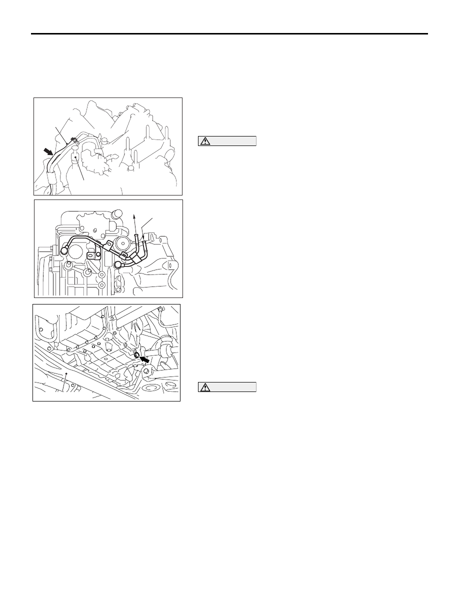
1. Disconnect the hose shown in the illustration which 

connects the transmission and the oil cooler (inside the 
radiator). Place a container under the hose to collect the 
discharge.

CAUTION

The engine should be stopped within one minute after it is 
started. If all the transmission fluid has drained out before 
then, the engine should be stopped at that point.
2. Start the engine and let the transmission fluid drain out.

(Running conditions: "N" range with engine idling)

Approximately 4.5 litres of transmission fluid should 
be removed.

3. Remove the drain plug from the bottom of the transmission 

case to drain the transmission fluid.

Approximately 1.0 litre of transmission fluid should be 
removed.

4. Install the drain plug with a new gasket, and tighten it to the 

specified torque.

Tightening torque: 32 

± 2 Nm (23 ± 2 ft-lb)

CAUTION

Stop pouring if the full volume of transmission fluid can 
not be added.
5. Add new transmission fluid (MITSUBISHI ATF SP III) 

through the oil filter tube.

Approximately 5.5 litres of transmission fluid should 
be added.

6. Repeat the procedure in Step 2. (to pump out the rest of the 

contaminated transmission fluid)

7. Add new transmission fluid (MITSUBISHI ATF SP III) 

through the oil filter tube.

Approximately 3.5 litres of transmission fluid should 
be added.

NOTE: Check for contamination or a burnt odor. If the trans-
mission fluid is still contaminated or burnt, repeat Steps 6 
and 7 before proceeding to Step 8.

10DB151A

DIPSTICK

INLET FROM

COOLER

10DB152A

TO 

COOLER

FROM

COOLER

AC306236

AB

CENTERMEMBER

<F4A4B>

ON-VEHICLE SERVICE

AUTOMATIC TRANSMISSION

23A-293

8. Reconnect the hose which was disconnected in step 1 

above, and firmly replace the dipstick.

9. Start the engine and run it at idle for one to two minutes.

10.Move the selector lever through all positions, and then move 

it to the "N" position.

11.Check that the transmission fluid level is at the "COLD" 

mark on the dipstick. If the level is less than this, add 
transmission fluid.

12.Drive the vehicle until the transmission fluid temperature 

rises to the normal operating temperature [70 

− 80°C (158 − 

176

°F)], and then check the transmission fluid level again. 

The transmission fluid level must be at the "HOT" mark.

NOTE: The transmission fluid temperature is measured with 
diagnostic tool MB991958 (MUT-III sub assembly).

NOTE: The "COLD" level is for reference only; the "HOT" 
level should be regarded as the standard level.

NOTE: If it takes some amount of time until the transmission 
fluid reaches its normal operating temperature [70 

 80°

(158 

 176°F)], check the transmission fluid level by refer-

ring to the left diagram.

13.When the transmission fluid is less than the specified level, 

add transmission fluid.
When the transmission fluid is greater than the specified 
level, drain the excess fluid through the drain plug to adjust 
the transmission fluid to the specified level.

14.Firmly insert the dipstick into the oil filler tube.

10DB151A

DIPSTICK

INLET FROM

COOLER

AC106828AB

AC005860

80

DIPSTICK

60

40

(176)

(140)

(104)

FLUID TEMPERATURE [˚C (˚F)]

– 30 (– 1.2)

– 20 (– 0.8)

– 10 (– 0.4)

0 (0)

10 (0.4)

FLUID LEVEL [mm (in)]

AB

ON-VEHICLE SERVICE

AUTOMATIC TRANSMISSION

23A-294

OIL COOLER FLOW CHECK

M1231013100214

After the new or repaired transmission has been installed, fill to 
the proper level with MITSUBISHI ATF SP III. The flow should 
be checked using the following procedure:

CAUTION

With the fluid set at the proper level, transmission fluid 
collection should not exceed one litre or internal damage 
to the transmission may occur.
1. Disconnect the OUTLET line (from cooler) at the 

transmission and place a collecting container under the 
disconnected line.

2. Run the engine at curb idle speed with the shift selector in 

neutral.

3. If transmission fluid flow is intermittent or it takes more than 

20 seconds to collect one litre of transmission fluid, replace 
the cooler.

4. If flow is within acceptable limits, reconnect the cooler line. 

Then fill the transmission to the proper level, using 
MITSUBISHI ATF SP III.

TRANSMISSION INHIBITOR SWITCH CHECK

M1231021600106

NOTE: For vehicles with sport mode, four positions (P, R, N, D) 
are used.

TRANSMISSION INHIBITOR SWITCH AND 
CONTROL CABLE ADJUSTMENT

M1231021700051

1. Set the selector lever to the "N" position.

10DB152A

TO 

COOLER

FROM

COOLER

TRANSMISSION 
RANGE

TERMINAL CONNECTION OF 
TESTER

SPECIFIED CONDITION

P

− 8, 9 − 10

Less than 2 ohms.

R

− 8

N

− 8, 9 − 10

D

− 8

10DB142A

P

R

N

D

10DB167A

B-110 (B)

TRANSMISSION

INHIBITOR SWITCH

ON-VEHICLE SERVICE

AUTOMATIC TRANSMISSION

23A-295

2. Loosen the control cable to the manual control lever 

coupling nut to free the cable and lever.

3. Set the manual control lever to the neutral position.

4. Loosen the transmission inhibitor switch body mounting 

bolts and turn the park/neutral position switch body so the 
hole in the end of the manual control lever and the hole 
(section A 

− A in the figure on the left) in the flange of the 

transmission inhibitor switch body flange are aligned.

5. Tighten the transmission inhibitor switch body mounting 

bolts to the specified torque. Be careful at this time that the 
switch body does not move.

Tightening torque: 11 

± 1 Nm (96 ± 8 in-lb)

6. Gently push the transmission control cable in the direction of 

the arrow, until the cable is taut. Tighten the adjusting nut.

Tightening torque: 12 

± 2 Nm (107 ± 17 in-lb)

7. Check that the selector lever is in the "N" position.

8. Check that each position of the manual control lever 

matches each position of the selector lever using diagnostic 
tool MB991958 (MUT-III sub assembly).

AUTOMATIC TRANSMISSION CONTROL 
COMPONENT CHECK

CRANKSHAFT POSITION SENSOR CHECK

M1231009000355

Refer to GROUP 13A <3.8L Engine>, Diagnosis 

− Inspection 

Procedure Using an Oscilloscope 

13A-652

.

10DB143A

12 ± 2 N·m
107 ± 17 in-lb

ADJUSTING NUT

MANUAL
CONTROL
LEVER

10DB144A

11 ± 1 N·m
96 ± 8 in-lb

MOUNTING BOLTS

MANUAL
CONTROL
LEVER

SECTION A - A

HOLE IN END

HOLE IN
FLANGE

TRANSMISSION 
RANGE SWITCH BODY

MANUAL
CONTROL
LEVER

10DB143A

12 ± 2 N·m
107 ± 17 in-lb

ADJUSTING NUT

MANUAL
CONTROL
LEVER


Content   ..  436  437  438  439   ..