Mitsubishi 380. Manual - part 432


  Index      Mitsubishi     Mitsubishi 380 - service repair manual 2005 year


Search            


Content   ..  430  431  432  433   ..


Mitsubishi 380. Manual - part 432


AUTOMATIC TRANSMISSION DIAGNOSIS

AUTOMATIC TRANSMISSION

23A-268

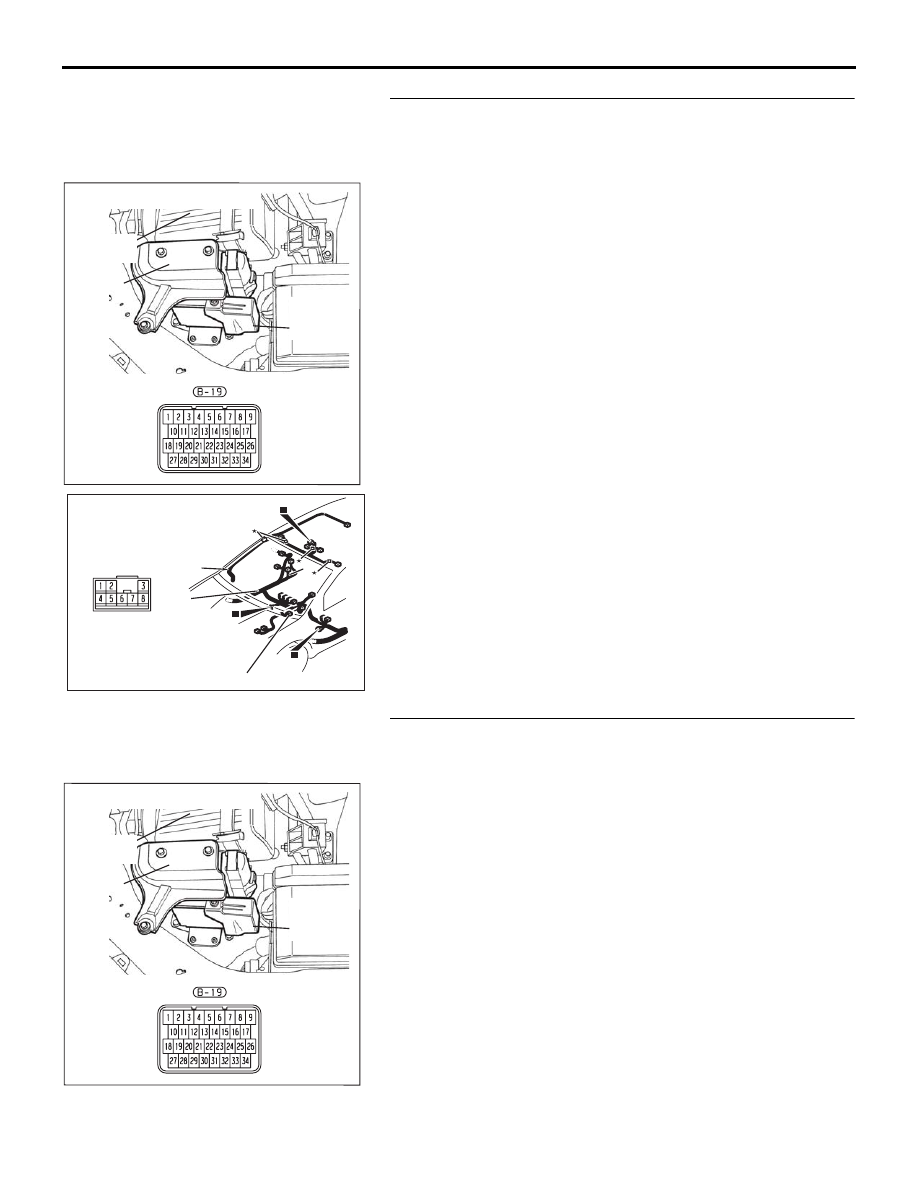
STEP 25. Check the harness for open circuit or short 
circuit to ground between A/T-ECU connector B-19 
terminal 9 and shift switch assembly connector D-14 
terminal 3.
Q: Is the harness wire in good condition?

YES : Go to Step 4.
NO :  Repair or replace the harness wire.

STEP 26. Check A/T-ECU connector B-19 for loose, 
corroded or damaged terminals, or terminals pushed back 
in the connector.
Q: Are the connector and terminals in good condition?

YES : Go to Step 4.
NO :  Repair or replace the damaged components. Refer to 

GROUP 00E, Harness Connector Inspection 

P.00E-2

.

10DB125A

COVER

AIR

CLEANER

A/T

CONTROL

UNIT

CONNECTOR:  B-19

10DB093A

CONNECTOR:  D-14

FLOOR

WIRING

HARNESS

4

Y

2

15

ROOF

WIRING

HARNESS

D-14

10DB125A

COVER

AIR

CLEANER

A/T

CONTROL

UNIT

CONNECTOR:  B-19

AUTOMATIC TRANSMISSION DIAGNOSIS

AUTOMATIC TRANSMISSION

23A-269

INSPECTION PROCEDURE 16: Shift Position Indicator Light System <Vehicles with Sport Mode>

.

CIRCUIT OPERATION

• The A/T-ECU detects the transmission range ("P," 

"R," "N," "D," sport mode "5", "4," "3," "2," or "1"), 
and display it on the combination meter.

.

COMMENT

Connector(s), wiring harness in the CAN bus line 
between the A/T-ECU and the combination meter, 
power supply to the A/T-ECU, the combination 
meter, the A/T-ECU may be defective.

.

TROUBLESHOOTING HINTS (The most 
likely causes for this condition:)

• Malfunction of the combination meter

• Damaged harness, connector

• Malfunction of the A/T-ECU

Circuit drawings

• Refer to circuit diagrams GROUP-

90

• Refer to configuration diagrams GROUP-

80

• Refer to component locations GROUP-

70

DIAGNOSIS

Required Special Tool:

• MB991958: Diagnostic Tool (MUT-III Sub Assembly)

• MB991824: V.C.I.

• MB991827: MUT-III USB Cable

• MB991910: MUT-III Main Harness A

STEP 1. Using diagnostic tool MB991958, diagnose the 
CAN bus line.

CAUTION

To prevent damage to diagnostic tool MB991958, always 
turn the ignition switch to the "LOCK" (OFF) position 
before connecting or disconnecting diagnostic tool 
MB991958.
Use diagnostic tool MB991958 to diagnose the CAN bus lines.
(1) Connect diagnostic tool MB991958 to the data link 

connector.

(2) Turn the ignition switch to the "ON" position.
(3) Diagnose the CAN bus line.
(4) Turn the ignition switch to the "LOCK" (OFF) position.

Q: Is the check result properly?

YES : Go to Step 2.
NO :  Repair the CAN bus lines (Refer to GROUP 54C, 

Diagnosis-CAN Bus Diagnostic Chart 

P.54C-15

).

00DB076A

MB991910

DATA LINK

CONNECTOR

MB991824

MB991827

AUTOMATIC TRANSMISSION DIAGNOSIS

AUTOMATIC TRANSMISSION

23A-270

STEP 2. Using diagnostic tool MB991958, read the MPI 
diagnostic trouble code.
(1) Connect diagnostic tool MB991958 to the data link 

connector.

(2) Turn the ignition switch to the "ON" position.
(3) Check for MPI diagnostic trouble code.
(4) Turn the ignition switch to the "LOCK" (OFF) position.

Q: Is DTC (U1108) set?

YES : Retry the troubleshooting procedures.
NO :  Replace the A/T-ECU.

00DB076A

MB991910

DATA LINK

CONNECTOR

MB991824

MB991827

AUTOMATIC TRANSMISSION DIAGNOSIS

AUTOMATIC TRANSMISSION

23A-271

DATA LIST REFERENCE TABLE

M1231008100337

MUT-III 
DIAGNOSTI
C TOOL 
DISPLAY

ITEM 
NO.

INSPECTION ITEM

INSPECTION 
REQUIREMENT

NORMAL 
CONDITION

2ND SOL 
DUTY

14

Second solenoid 
valve duty %

Transmission range:  
Sport mode 
<Vehicles with sport 
mode>

Driving at constant 
speed of 10 km/h (6.2 
mph) in 1st gear

100%

Transmission range:  
Sport mode 
<Vehicles with sport 
mode>

Driving at constant 
speed of 30 km/h (19 
mph) in 2nd gear

0%

Transmission range:  
Sport mode 
<Vehicles with sport 
mode>

Driving at constant 
speed of 50 km/h (31 
mph) in 3rd gear

100%

Transmission range:  
Sport mode 
<Vehicles with sport 
mode>

Driving at constant 
speed of 50 km/h (31 
mph) in 4th gear

100%

Transmission range:  
Sport mode 
<Vehicles with sport 
mode>

Driving at constant 
speed of 50 km/h (31 
mph) in 5th gear

0%

A/T CONT 
RLY

8

A/T control relay 
output voltage (V)

Ignition switch: ON

Battery voltage

ENGINE 
SPEED

1

ENGINE SPEED 
(r/min)

Accelerator pedal: 
Release

600 

− 900 

r/min

Accelerator pedal: 
Depressed

Gradually rises 
from the above 
value

A/C 
Compressor 
Relay

21

A/C Compressor 
Relay

• Engine: Idling

• Transmission 

range: P, N

A/C switch: ON (while 
the A/C compressor is 
in operation)

ON

A/C switch: OFF

OFF

ISS SENSOR 5

Input shaft speed 
sensor (r/min)

Gear range: 4th gear Driving at constant 

speed of 50 km/h (31 
mph)

1,100 

− 1,400 

r/min


Content   ..  430  431  432  433   ..