Mitsubishi 380. Manual - part 426


  Index      Mitsubishi     Mitsubishi 380 - service repair manual 2005 year


Search            


Content   ..  424  425  426  427   ..


Mitsubishi 380. Manual - part 426


AUTOMATIC TRANSMISSION DIAGNOSIS

AUTOMATIC TRANSMISSION

23A-244

INSPECTION PROCEDURE 12: No Diagnostic Trouble Codes (Does not Shift)

.

CIRCUIT OPERATION

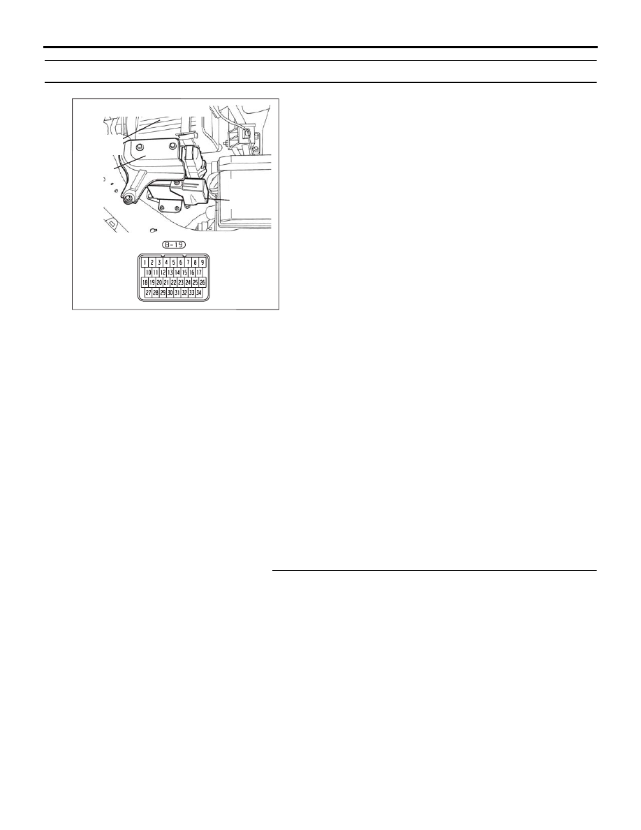
A/T-ECU connector B-19 (terminal number 21) 
receives battery positive voltage from the battery.

.

COMMENT

If shifting does not occur while driving and no diag-
nostic trouble codes are output, a malfunction of the 
transmission inhibitor switch, or A/T-ECU may exist.

.

TROUBLESHOOTING HINTS (The most 
likely causes for this condition:)

• Malfunction of the transmission inhibitor switch

• Damaged harness, connector

• Malfunction of the A/T-ECU

Circuit drawings

• Refer to circuit diagrams GROUP-

90

• Refer to configuration diagrams GROUP-

80

• Refer to component locations GROUP-

70

DIAGNOSIS

Required Special Tool:

• MB991958: Diagnostic Tool (MUT-III Sub Assembly)

• MB991824: V.C.I.

• MB991827: MUT-III USB Cable

• MB991910: MUT-III Main Harness A

STEP 1. Check the vehicle acceleration.

Q: Does the vehicle accelerate poorly (transmission stays 

in 3rd gear) when starting from a stop with the selector 
lever in "D" range?
YES : 
Go to Step 2.
NO :  Go to Step 5.

10DB125A

COVER

AIR

CLEANER

A/T

CONTROL

UNIT

CONNECTOR:  B-19

AUTOMATIC TRANSMISSION DIAGNOSIS

AUTOMATIC TRANSMISSION

23A-245

STEP 2. Measure the backup power supply voltage at 
A/T-ECU connector B-19 by using check harness special 
tool MB992045.
(1) Disconnect all the connectors from the A/T-ECU.

(2) Connect special tool MB992045 (check harness) between 

the A/T-ECU and the body-side harness connector.

(3) Turn the ignition switch to the "ON" position.

(4) Measure the voltage between connector B-19 terminal 21 

and ground.

• The voltage should measure battery positive voltage.

(5) Turn the ignition switch to the "LOCK" (OFF) position.

Q: Is the measured voltage battery positive voltage?

YES : Go to Step 5.
NO :  Go to Step 3.

10DB125A

COVER

AIR

CLEANER

A/T

CONTROL

UNIT

CONNECTOR:  B-19

10DB161A

A/T-ECU CHECK HARNESS
    MB992045

A/T-ECU

A/T-ECU CHECK 
HARNESS
CONNECTORS

10DB124A

B-19 HARNESS 

CONNECTOR: 

AUTOMATIC TRANSMISSION DIAGNOSIS

AUTOMATIC TRANSMISSION

23A-246

STEP 3. Check A/T-ECU connector B-19 for loose, 
corroded or damaged terminals, or terminals pushed back 
in the connector.
Q: Is the connector in good condition?

YES : Go to Step 4.
NO :  Repair or replace the damaged components. Refer to 

GROUP 00E, Harness Connector Inspection 

P.00E-2

. Then retest the system.

STEP 4. Check the harness for open circuit between 
A/T-ECU connector B-19 terminal 21 and battery.
Q: Is the harness wire in good condition?

YES : Go to Step 5.
NO :  Repair or replace the harness wire.

16DB564A

COVER

AIR

CLEANER

A/T

CONTROL

UNIT

CONNECTORS:  B-19, B-22

10DB125A

COVER

AIR

CLEANER

A/T

CONTROL

UNIT

CONNECTOR:  B-19

AUTOMATIC TRANSMISSION DIAGNOSIS

AUTOMATIC TRANSMISSION

23A-247

STEP 5. Using diagnostic tool MB991958, check data list 
item 34: Inhibitor Switch.

CAUTION

To prevent damage to diagnostic tool MB991958, always 
turn the ignition switch to the "LOCK" (OFF) position 
before connecting or disconnecting diagnostic tool 
MB991958.
(1) Connect diagnostic tool MB991958 to the data link 

connector.

(2) Turn the ignition switch to the "ON" position.
(3) Set diagnostic tool MB991958 to the data reading mode.

• Item 34: Inhibitor Switch.

• Item 27: Sports mode select switch

• Item 28: Sports mode upshift switch

• Item 29: Sports mode downshift switch

• Move the selector lever positions and confirm that 

the selected transmission range match the positions 
shown on diagnostic tool MB991958.

(4) Turn the ignition switch to the "LOCK" (OFF) position.

Q: Is the switch operating properly?

YES : Check for the symptom. If the symptom is not 

eliminated, replace the A/T-ECU.

NO :  Refer to 

P.23A-97

P.23A-119

, (P0705): Transmission 

Inhibitor Switch system, and refer to inspection 
procedure 15 (Sports mode switch system)

00DB076A

MB991910

DATA LINK

CONNECTOR

MB991824

MB991827


Content   ..  424  425  426  427   ..