Mitsubishi 380. Manual - part 364
KNUCKLE
REAR AXLE
27-8
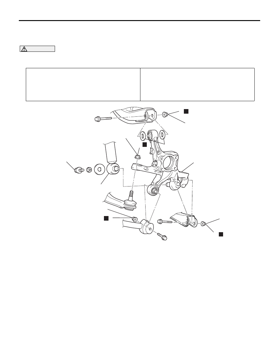
KNUCKLE
REMOVAL AND INSTALLATION
M1271003000191
CAUTION
*
: Indicates parts which should be temporarily tightened, and then fully tightened with the vehicle on
the ground in the unladen condition.
Required Special Tool:
MB991897: Ball Joint Remover
Pre-removal Operation
• Rear Axle Hub Assembly Removal (Refer to
• Parking Brake Assembly Removal (Refer to GROUP 36,
Parking Brake Lining and Drum
).
Post-installation Operation
• Check the ball joint dust cover for cracks or damage by
pushing it with your finger.
• Parking Brake Assembly Installation (Refer to GROUP
36, Parking Brake Lining and Drum
• Rear Axle Hub Assembly Installation (Refer to
AC308327
N
66 ± 6 N·m
49 ± 4 ft-lb
4
2
3
5
6
1
N
N
N
113 ± 12 N·m*
83 ± 9 ft-lb*
113 ± 12 N·m*
83 ± 9 ft-lb*
113 ± 12 N·m*
83 ± 9 ft-lb*
100 ± 10 N·m
74 ± 7 ft-lb
AB
7
REMOVAL STEPS
1.
SELF LOCKING NUT (TRAILING
ARM CONNECTION)
<<A>>
2.
SELF LOCKING NUT (TOE
CONTROL ARM CONNECTION)
3.
SHOCK ABSORBER
CONNECTION
4.
SELF LOCKING NUT (LOWER
ARM CONNECTION)
5.
SELF LOCKING NUT (UPPER
ARM CONNECTION)
6.
KNUCKLE
7.
UPPER ARM STOPPER
REMOVAL STEPS (Continued)