Mitsubishi 380. Manual - part 355
GENERAL DESCRIPTION
FRONT AXLE
26-2
GENERAL DESCRIPTION
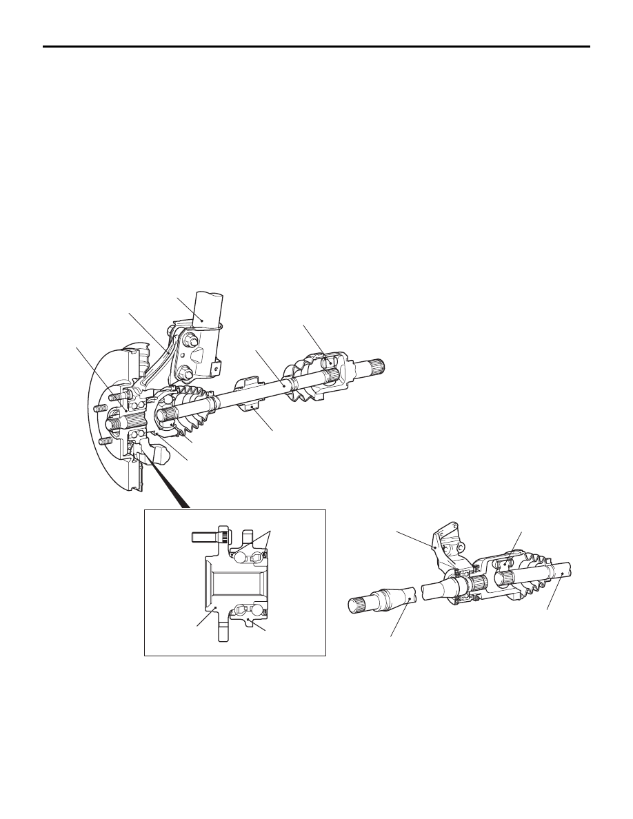
M1261000100370
The front axle consists of front hubs, knuckles, wheel
bearings and drive shafts, and has the following fea-
tures:
• The wheel bearing incorporates double-row
angular contact ball bearing for reduced friction.
• The front wheel hub assembly combines the hub,
wheel bearing, and oil seal in a single unit for
fewer parts, better durability, improved assembly
precision, and better structural organization.
• The driveshaft incorporates BJ-PTJ type constant
velocity joints with high transmission efficiency for
low vibration and noise.
• Due to the use of the inner shaft and bracket
assembly, the right and left drive shafts are
approximately the same in length. This reduces
noise, vibration and torque steer.L-RH>
• The dynamic damper is mounted on the LH drive-
shaft.
• ABS rotor for detecting the wheel speed is
press-fitted to the BJ.
NOTE:
.
• TJ: Tripod Joint
• PTJ: Pillow Tripod Joint
• BJ: Birfield Joint
CONSTRUCTION DIAGRAM
FRONT AXLE DIAGNOSIS
TROUBLESHOOTING STRATEGY
M1261005600240
Use these steps to plan your diagnostic strategy. If
you follow them carefully, you will be sure that you
have exhausted most of the possible ways to find a
front axle fault.
1. Gather information from the customer.
22DB013A
FRONT WHEEL
HUB ASSEMBLY
KNUCKLE
STRUT ASSEMBLY
PTJ (LH) <3.8L>
DRIVE SHAFT
(LH)
BJ
BRACKET
ASSEMBLY
DRIVE SHAFT (RH)
PTJ (RH)
INNER SHAFT
ABS ROTOR
DYNAMIC
DAMPER
<L-RH>
WHEEL
BEARING
OIL
SEAL
HUB