Mitsubishi 380. Manual - part 348


  Index      Mitsubishi     Mitsubishi 380 - service repair manual 2005 year


Search            


Content   ..  346  347  348  349   ..


Mitsubishi 380. Manual - part 348


AUTO-CRUISE CONTROL

ENGINE AND EMISSION CONTROL

17-60

INSPECTION PROCEDURE 6: Hunting (Repeated Acceleration and Deceleration) Occurs at the Set 
Vehicle Speed.

.

COMMENT

The output shaft speed sensor signal or the throttle 
body is suspected.

.

TROUBLESHOOTING HINTS (THE MOST 
LIKELY CAUSES FOR THIS CASE:)

• Malfunction of the output shaft speed sensor.

• Malfunction of the throttle body.

• Malfunction of the Engine ECU.

• Malfunction of the A/T ECU.

Circuit drawings

• Refer to circuit diagrams GROUP-

90

• Refer to configuration diagrams GROUP-

80

• Refer to component locations GROUP-

70

DIAGNOSIS

Required Special Tools:

• MB991958: Diagnostic Tool (MUT-III Sub Assembly)

• MB991824: V.C.I.

• MB991827: MUT-III USB Cable

• MB991910: MUT-III Main Harness A

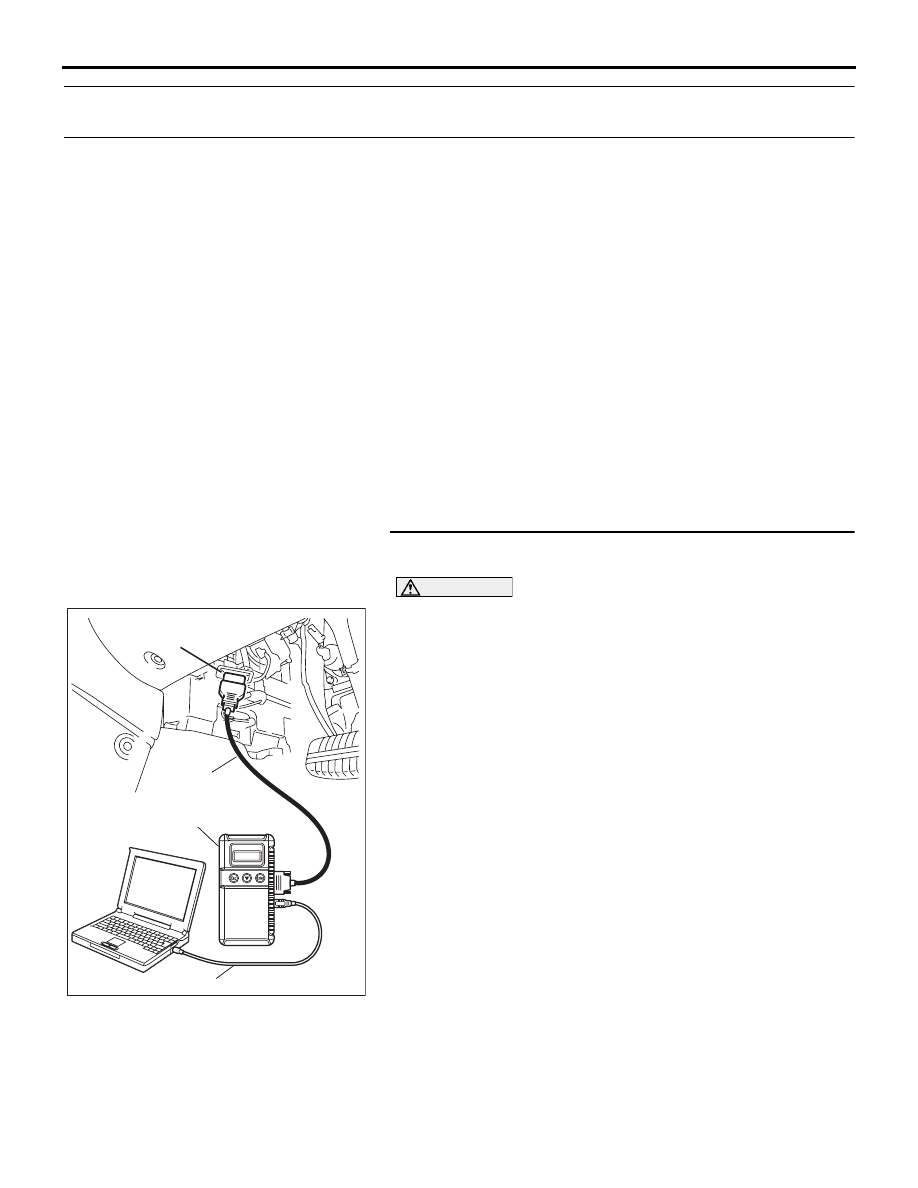
STEP 1. Using Diagnostic Tool MB991958, read the 
diagnostic trouble code.

CAUTION

To prevent damage to Diagnostic Tool MB991958, always 
turn the ignition switch to the "LOCK" (OFF) position 
before connecting or disconnecting Diagnostic Tool 
MB991958.
(1) Connect Diagnostic Tool MB991958 to the data link 

connector. (Refer to 

P.17-11

).

(2) Turn the ignition switch to the "ON" position.
(3) Check for A/T system diagnostic trouble code. (Refer to 

GROUP 23A, A/T Diagnosis 

− Diagnostic Function − How 

to Read and Erase Diagnostic Trouble Code 

P.23A-13

).

(4) Turn the ignition switch to the "LOCK" (OFF) position.
(5) Disconnect Diagnostic Tool MB991958.

Q: Is any DTC set?

YES : Diagnose the A/T system. (Refer to GROUP 23A, A/T 

Diagnosis 

− Diagnostic Trouble Code Chart 

P.23A-34

). Then go to Step 4.

NO :  Go to Step 2.

00DB076A

MB991910

DATA LINK

CONNECTOR

MB991824

MB991827

AUTO-CRUISE CONTROL

ENGINE AND EMISSION CONTROL

17-61

STEP 2. Using Diagnostic Tool MB991958, read the 
diagnostic trouble code.

CAUTION

To prevent damage to Diagnostic Tool MB991958, always 
turn the ignition switch to the "LOCK" (OFF) position 
before connecting or disconnecting Diagnostic Tool 
MB991958.
(1) Connect Diagnostic Tool MB991958 to the data link 

connector. (Refer to 

P.17-11

).

(2) Turn the ignition switch to the "ON" position.
(3) Check for MPI system diagnostic trouble code(Refer to 

GROUP 13A, MPI Diagnosis 

− Diagnostic Function − How 

to Read and Erase Diagnostic Trouble Code 

13A-6

).

(4) Turn the ignition switch to the "LOCK" (OFF) position.
(5) Disconnect Diagnostic Tool MB991958.

Q: Is any DTC set?

YES : Diagnose the MPI system. (Refer to GROUP 13A, 

MPI Diagnosis 

− Diagnostic Trouble Code Chart 

13A-17

). Then go to Step 4.

NO :  Go to Step 3.

STEP 3. Retest the system

Q: Does hunting occur?

YES : Replace the Engine ECU[Refer to GROUP 13A, 

Engine ECU 

13A-675

]. Then go to Step 4.

NO :  It can be assumed that this malfunction is intermittent. 

(Refer to GROUP 00, How to Use 
Troubleshooting/Inspection Service Points 

− How to 

Cope with Intermittent Malfunction 

P.00-14

).

STEP 4. Retest the system

Q: Does hunting occur?

YES : Return to Step 1.
NO :  The procedure is complete.

00DB076A

MB991910

DATA LINK

CONNECTOR

MB991824

MB991827

AUTO-CRUISE CONTROL

ENGINE AND EMISSION CONTROL

17-62

INSPECTION PROCEDURE 7: When "CRUISE" (MAIN) Switch is Turned "ON", "CRUISE" Indicator 
Light Inside Combination Meter does not Illuminate. (However, Auto-cruise Control System is 
Normal).

.

16DB402A

A-02 (GR)

CONNECTOR: A-02 

A-02 HARNESS CONNECTOR:

16DB400A

COVER

ENGINE

CONTROL

UNIT

AIR

CLEANER

17DB046A

C-29

C-101

C-02

C-02 HARNESS

CONNECTOR:

COMPONENT SIDE

C-29 MALE SIDE

CONNECTOR

C-101 HARNESS

CONNECTOR:

COMPONENT SIDE

CONNECTORS: C-02, C-29, C-101

17DB047A

C-215 HARNESS CONNECTOR:

COMPONENT SIDE

CONNECTORS: C-211, C-215

C-211 HARNESS CONNECTOR:

COMPONENT SIDE

AUTO-CRUISE CONTROL

ENGINE AND EMISSION CONTROL

17-63

CIRCUIT OPERATION

The Engine ECU detects "CRUISE" (MAIN) switch 
"ON" signal to illuminate the "CRUISE" indicator 
lamp on the combination meter.

.

COMMENT

Connector(s), wiring harness in the CAN bus line 
between the Engine ECU and the combination 
meter, power supply to the Engine ECU, the combi-
nation meter, the Engine ECU may be defective.

.

TROUBLESHOOTING HINTS

• Malfunction of the combination meter.

• Damaged harness or connector.

• Malfunction of the Engine ECU.

Circuit drawings

• Refer to circuit diagrams GROUP-

90

• Refer to configuration diagrams GROUP-

80

• Refer to component locations GROUP-

70

DIAGNOSIS

Required Special Tools:

• MB991958: Diagnostic Tool (MUT-III Sub Assembly)

• MB991824: V.C.I.

• MB991827: MUT-III USB Cable

• MB991910: MUT-III Main Harness A

STEP 1. Using Diagnostic Tool MB991958, diagnose the 
CAN bus line.

CAUTION

To prevent damage to Diagnostic Tool MB991958, always 
turn the ignition switch to the "LOCK" (OFF) position 
before connecting or disconnecting Diagnostic Tool 
MB991958.
(1) Connect Diagnostic Tool MB991958 to the data link 

connector. (Refer to 

P.17-11

).

(2) Turn the ignition switch to the "ON" position.
(3) Diagnose the CAN bus line. (Refer to 

P.17-11

).

(4) Turn the ignition switch to the "LOCK" (OFF) position.
(5) Disconnect Diagnostic Tool MB991958.

Q: Is the check result satisfactory?

YES : Go to Step 2
NO :  Repair the CAN bus lines. (Refer to GROUP 54C, 

Diagnosis 

− Can Bus Diagnostic Char

P.54C-15

). 

Then go to Step 4.

00DB076A

MB991910

DATA LINK

CONNECTOR

MB991824

MB991827


Content   ..  346  347  348  349   ..