Mitsubishi 380. Manual - part 344
AUTO-CRUISE CONTROL
ENGINE AND EMISSION CONTROL
17-44
STEP 13. Using Diagnostic Tool MB991958, check data list
item 74: Stoplamp Switch.
CAUTION
To prevent damage to Diagnostic Tool MB991958, always
turn the ignition switch to the "LOCK" (OFF) position
before connecting or disconnecting Diagnostic Tool
MB991958.
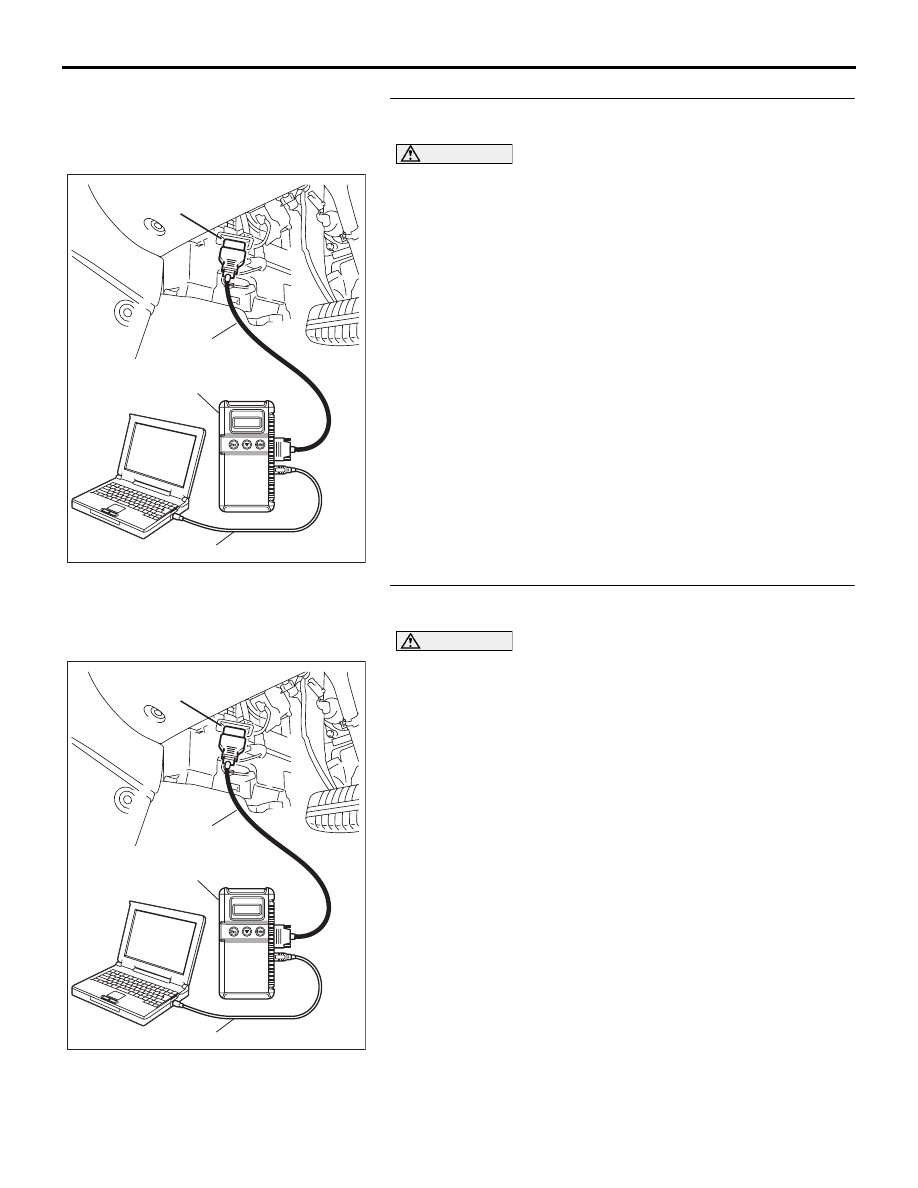
(1) Connect Diagnostic Tool MB991958 to the data link
(2) Turn the ignition switch to the "ON" position.
(3) Set Diagnostic Tool MB991958 to data reading mode for
auto-cruise control system. (Refer to
• Item 74, Stoplamp Switch.
• When the brake pedal is depressed, the display on
Diagnostic Tool MB991958 should be "ON".
• When the brake pedal is released, the display on
Diagnostic Tool MB991958 should be "OFF".
(4) Turn the ignition switch to the "LOCK" (OFF) position.
(5) Disconnect Diagnostic Tool MB991958.
Q: Is the switch operating properly?
YES : Go to Step 21.
NO : Replace the Engine ECU. [Refer to GROUP 13A,
Engine ECU
STEP 14. Using Diagnostic Tool MB991958, check data list
item 89: Normally closed Brake Switch.
CAUTION
To prevent damage to Diagnostic Tool MB991958, always
turn the ignition switch to the "LOCK" (OFF) position
before connecting or disconnecting Diagnostic Tool
MB991958.
(1) Connect Diagnostic Tool MB991958 to the data link
(2) Turn the ignition switch to the "ON" position.
(3) Set Diagnostic Tool MB991958 to data reading mode for
auto-cruise control system. (Refer to
• Item 89, Normally closed Brake Switch.
• When the brake pedal is depressed, the display on
Diagnostic Tool MB991958 should be "ON".
• When the brake pedal is released, the display on
Diagnostic Tool MB991958 should be "OFF".
(4) Turn the ignition switch to the "LOCK" (OFF) position.
(5) Disconnect Diagnostic Tool MB991958.
Q: Is the switch operating properly?
YES : Go to Step 21.
NO : Go to Step 15.
00DB076A
MB991910
DATA LINK
CONNECTOR
MB991824
MB991827
00DB076A
MB991910
DATA LINK
CONNECTOR
MB991824
MB991827