Mitsubishi 380. Manual - part 323


  Index      Mitsubishi     Mitsubishi 380 - service repair manual 2005 year


Search            


Content   ..  321  322  323  324   ..


Mitsubishi 380. Manual - part 323


TRACTION CONTROL SYSTEM (TCL) DIAGNOSIS

TRACTION CONTROL SYSTEM (TCL)

13C-12

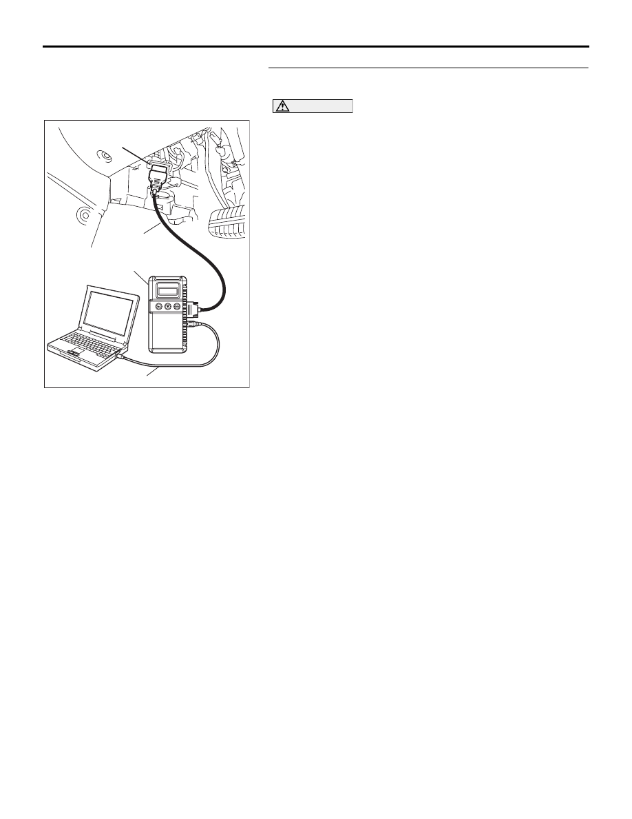
STEP 3. Using diagnostic tool MB991958, read the 
diagnostic trouble code.

CAUTION

To prevent damage to diagnostic tool MB991958, always 
turn the ignition switch to the "LOCK" (OFF) position 
before connecting or disconnecting diagnostic tool 
MB991958.
(1) Connect diagnostic tool MB991958 to the data link 

connector. (Refer to 

P.13C-3

).

(2) Turn the ignition switch to the "ON" position.
(3) Check if a DTC, which relates to CAN 

communication-linked systems below, is set.
ETACS-ECU

• DTC (U1100): ENGINE-ECU time-out (related to 

engine). (Refer to GROUP 54B, SWS Diagnosis 

− 

General Description 

− Diagnostic Function − How to 

Read and Erase Diagnostic Trouble Code 

P.54B-10

).

Combination meter

• DTC (U1100): ENGINE-ECU time-out (related to 

engine). (Refer to GROUP 54A, Combination Meter 
Assembly Diagnosis 

− Diagnosis Function − How to 

Read and Erase Diagnostic Trouble Code 

P.54A-46

).

Multi-center display

• DTC (U1100): ENGINE-ECU time-out (related to 

engine). (Refer to GROUP 54A, Multi-center Display 
− Diagnosis Function − How to Read and Erase 
Diagnostic Trouble Code 

P.54A-251

).

A/C-ECU

• DTC (U1100): ENGINE-ECU time-out (related to 

engine). (Refer to GROUP 55, Auto A/C Diagnosis 

− 

Diagnostic Function 

− How to Read and Erase Diag-

nostic Trouble Code 

P.55-6

) <Vehicle with auto 

A/C>.

(4) Turn the ignition switch to the "LOCK" (OFF) position.
(5) Disconnect diagnostic tool MB991958.

Q: Is DTC (U1100) set?

YES : Go to Step 4.
NO :  Go to Step 5.

00DB076A

MB991910

DATA LINK

CONNECTOR

MB991824

MB991827

TRACTION CONTROL SYSTEM (TCL) DIAGNOSIS

TRACTION CONTROL SYSTEM (TCL)

13C-13

STEP 4. Using diagnostic tool MB991958, read the 
diagnostic trouble code.

CAUTION

To prevent damage to diagnostic tool MB991958, always 
turn the ignition switch to the "LOCK" (OFF) position 
before connecting or disconnecting diagnostic tool 
MB991958.
(1) Connect diagnostic tool MB991958 to the data link 

connector. (Refer to 

P.13C-3

).

(2) Turn the ignition switch to the "ON" position.
(3) Use diagnostic tool MB991958 to read the TCL diagnostic 

trouble codes. (Refer to 

P.13C-3

).

(4) Turn the ignition switch to the "LOCK" (OFF) position.
(5) Disconnect diagnostic tool MB991958.

Q: Is DTC U1100 set?

YES : Replace the Engine-ECU. [Refer to GROUP 13A, 

Engine-ECU 

P.13A-675

]. Then go to Step 6.

NO :  It can be assumed that this malfunction is intermittent. 

(Refer to GROUP 00, How to Use 
Troubleshooting/Inspection Service Points 

− How to 

Cope with Intermittent Malfunction 

P.00-14

).

STEP 5. Using diagnostic tool MB991958, read the 
diagnostic trouble code.

CAUTION

To prevent damage to diagnostic tool MB991958, always 
turn the ignition switch to the "LOCK" (OFF) position 
before connecting or disconnecting diagnostic tool 
MB991958.
(1) Connect diagnostic tool MB991958 to the data link 

connector. (Refer to 

P.13C-3

).

(2) Turn the ignition switch to the "ON" position.
(3) Use diagnostic tool MB991958 to read the TCL diagnostic 

trouble codes. (Refer to 

P.13C-3

).

(4) Turn the ignition switch to the "LOCK" (OFF) position.
(5) Disconnect diagnostic tool MB991958.

Q: Is DTC U1100 set?

YES : Replace the hydraulic unit (integrated with 

ABS/TCL-ECU). (Refer to GROUP 35B 

− Hydraulic 

Unit 

P.35B-93

). Then go to Step 6.

NO :  It can be assumed that this malfunction is intermittent. 

(Refer to GROUP 00, How to Use 
Troubleshooting/Inspection Service Points 

− How to 

Cope with Intermittent Malfunction 

P.00-14

).

00DB076A

MB991910

DATA LINK

CONNECTOR

MB991824

MB991827

00DB076A

MB991910

DATA LINK

CONNECTOR

MB991824

MB991827

TRACTION CONTROL SYSTEM (TCL) DIAGNOSIS

TRACTION CONTROL SYSTEM (TCL)

13C-14

STEP 6. Using diagnostic tool MB991958, read the 
diagnostic trouble code.

CAUTION

To prevent damage to diagnostic tool MB991958, always 
turn the ignition switch to the "LOCK" (OFF) position 
before connecting or disconnecting diagnostic tool 
MB991958.
(1) Connect diagnostic tool MB991958 to the data link 

connector. (Refer to 

P.13C-3

).

(2) Turn the ignition switch to the "ON" position.
(3) Use diagnostic tool MB991958 to read the TCL diagnostic 

trouble codes. (Refer to 

P.13C-3

).

(4) Turn the ignition switch to the "LOCK" (OFF) position.
(5) Disconnect diagnostic tool MB991958.

Q: Is DTC U1100 set?

YES : Return to Step 1.
NO :  The procedure is complete.

U1101 CAN Communications System Time Out Error A/T Related Data

CAUTION

• If DTC U1101 is set in the ABS/TCL-ECU, 

always diagnose the CAN main bus line. If 
there is any fault in the CAN bus lines, an 
incorrect DTC may be set.

• Whenever the ABS/TCL-ECU is replaced, 

ensure that the communication circuit is nor-
mal.

NOTE: If the ABS-8 ECU or the active wheel 
speed sensor are disconnected, or if the wiring is 
an open/ short circuit, the ABS 8 ECU will shut 
off power supply to the respective wheel speed 
sensor. All other wheel speed sensors will oper-
ate normally. To restore the power supply, the 
ignition switch must be turned to the "OFF" posi-
tion then to the "ON" position again.

.

DTC SET CONDITION

The ABS/TCL-ECU receives A/T system-related sig-
nals from the A/T-ECU via CAN bus lines.

.

TROUBLESHOOTING HINTS (THE MOST 
LIKELY CAUSES FOR THESE DTCS ARE 
TO SET ARE:)

• Damaged harness or connector.

• Malfunction of the A/T-ECU.

• Malfunction of the ABS/TCL-ECU.

DIAGNOSIS

Required Special Tools:

• MB991958: Diagnostic Tool (MUT-III Sub Assembly)

• MB991824: V.C.I.

• MB991827: MUT-III USB Cable

• MB991910: MUT-III Main Harness A

00DB076A

MB991910

DATA LINK

CONNECTOR

MB991824

MB991827

TRACTION CONTROL SYSTEM (TCL) DIAGNOSIS

TRACTION CONTROL SYSTEM (TCL)

13C-15

STEP 1. Using diagnostic tool MB991958, diagnose the 
CAN bus line.

CAUTION

To prevent damage to diagnostic tool MB991958, always 
turn the ignition switch to the "LOCK" (OFF) position 
before connecting or disconnecting diagnostic tool 
MB991958.
(1) Connect diagnostic tool MB991958 to the data link 

connector. (Refer to 

P.13C-3

).

(2) Turn the ignition switch to the "ON" position.
(3) Diagnose the CAN bus line. (Refer to 

P.13C-3

).

(4) Turn the ignition switch to the "LOCK" (OFF) position.
(5) Disconnect diagnostic tool MB991958.

Q: Is the CAN bus line found to be normal?

YES : Go to Step 2.
NO :  Repair the CAN bus lines. (Refer to GROUP 54C, 

Diagnosis 

− Can Bus Diagnostic Char

P.54C-15

). 

Then go to Step 6.

STEP 2. Using diagnostic tool MB991958, read the 
diagnostic trouble code.

CAUTION

To prevent damage to diagnostic tool MB991958, always 
turn the ignition switch to the "LOCK" (OFF) position 
before connecting or disconnecting diagnostic tool 
MB991958.
(1) Connect diagnostic tool MB991958 to the data link 

connector. (Refer to 

P.13C-3

).

(2) Turn the ignition switch to the "ON" position.
(3) Check for A/T system diagnostic trouble code. (Refer to 

GROUP 23A, A/T Diagnosis 

− Diagnostic Function − How 

to Read and Erase Diagnostic Trouble Code 

P.23A-13

).

(4) Turn the ignition switch to the "LOCK" (OFF) position.
(5) Disconnect diagnostic tool MB991958.

Q: Is any DTC set?

YES : Repair the automatic transaxle control system. (Refer 

to GROUP 23A, A/T Diagnosis 

− Diagnostic Trouble 

Code Chart 

P.23A-34

). Then go to Step 6.

NO :  Go to Step 3.

00DB076A

MB991910

DATA LINK

CONNECTOR

MB991824

MB991827

00DB076A

MB991910

DATA LINK

CONNECTOR

MB991824

MB991827


Content   ..  321  322  323  324   ..