Mitsubishi 380. Manual - part 231


  Index      Mitsubishi     Mitsubishi 380 - service repair manual 2005 year


Search            


Content   ..  229  230  231  232   ..


Mitsubishi 380. Manual - part 231


ENGINE COOLING DIAGNOSIS

ENGINE COOLING

14-8

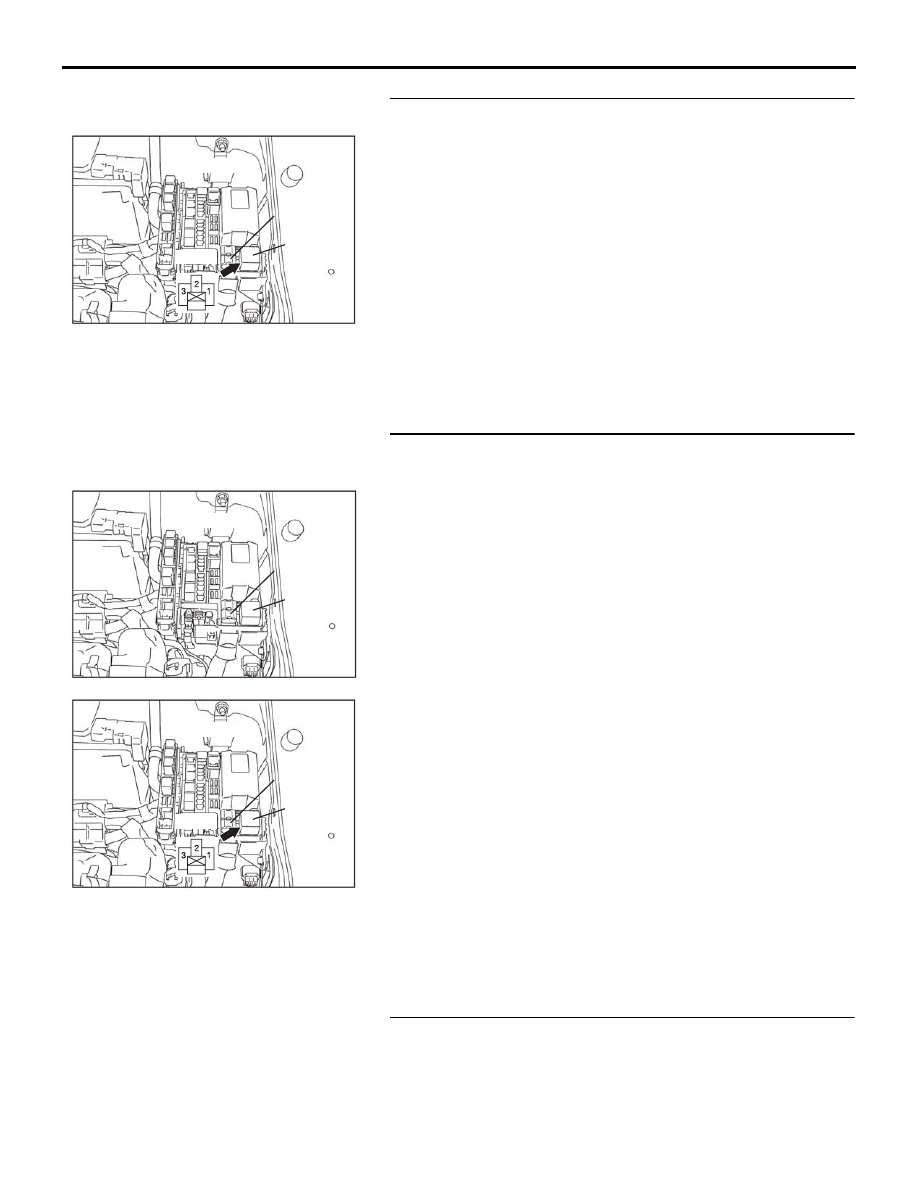
STEP 5. Check the fan control relay connector A-10X.

Q: Is the connector in good condition?

YES : Go to Step 6.
NO :  Repair the connector or replace the relay box. Then 

go to Step 24.

STEP 6. Check the harness wire between fusible link No.2 
and fan control relay connector A-10X terminal 4.

Q: Is the harness wire in good condition?

YES : An intermittent malfunction is suspected (Refer to 

GROUP 00 - How to use troubleshooting 

00-7

).

NO :  Repair the damaged harness wire. Then go to Step 

24.

STEP 7. Check the fan control relay.
Refer to 

14-31

.

Q: Is the fan control relay in good condition?

YES : Go to Step 8.
NO :  Replace the fan control relay. Then go to Step 24.

04DB012A

Fusible link

No.2

Relay box

Fan control

relay

A-10X

4

04DB010A

Fusible link

No.2

Relay box

Fan control

relay

04DB012A

Fusible link

No.2

Relay box

Fan control

relay

A-10X

4

ENGINE COOLING DIAGNOSIS

ENGINE COOLING

14-9

STEP 8. Check the fan control relay connector A-10X.

Q: Is the connector in good condition?

YES : Go to Step 9.
NO :  Repair the connector or replace the relay box. Then 

go to Step 24.

STEP 9. Check the harness wire between fan control relay 
connector A-10X terminal 2 and fan controller connector 
A-24 terminal 3.

Q: Is the harness wire in good condition?

YES : Go to Step 10.
NO :  Repair the damaged harness wire. Then go to Step 

24.

04DB012A

Fusible link

No.2

Relay box

Fan control

relay

A-10X

4

04DB012A

Fusible link

No.2

Relay box

Fan control

relay

A-10X

4

04DB008A

1

2

3

A-24

Connector: A-24

ENGINE COOLING DIAGNOSIS

ENGINE COOLING

14-10

STEP 10. Measure the terminal voltage at fan control relay 
connector A-10X.

(1) Disconnect fan control relay connector A-10X (remove the 

fan control relay) and measure relay box side connector.

(2) Turn the ignition switch to the "ON" position.

(3) Measure the voltage between fan control relay connector 

A-10X terminal 3 and body earth.

• The voltage should measure system voltage.

(4) Turn the ignition switch to the "LOCK" (OFF) position.
(5) Connect fan control relay connector A-10X (install the fan 

control relay).

Q: Is the measured voltage system voltage?

YES : Go to Step 13.
NO :  Go to Step 11.

04DB012A

Fusible link

No.2

Relay box

Fan control

relay

A-10X

4

04DB014A

A-10X Connector

(Relay box side)

ENGINE COOLING DIAGNOSIS

ENGINE COOLING

14-11

STEP 11. Check the ECU connector B-21, intermediate 
connector A-13 and fan control relay connector A-10X. 

Q: Are there connectors in good condition?

YES : Go to Step 12.
NO :  Repair or replace the connector. Then go to Step 24.

16DB400A

COVER

ENGINE

CONTROL

UNIT

AIR

CLEANER

AK303148

CONNECTOR: A-13

AB

A-13(GR)

04DB012A

Fusible link

No.2

Relay box

Fan control

relay

A-10X

4


Content   ..  229  230  231  232   ..