Mitsubishi 380. Manual - part 228
HOW TO DIAGNOSE
GENERAL <ELECTRICAL>
00E-10
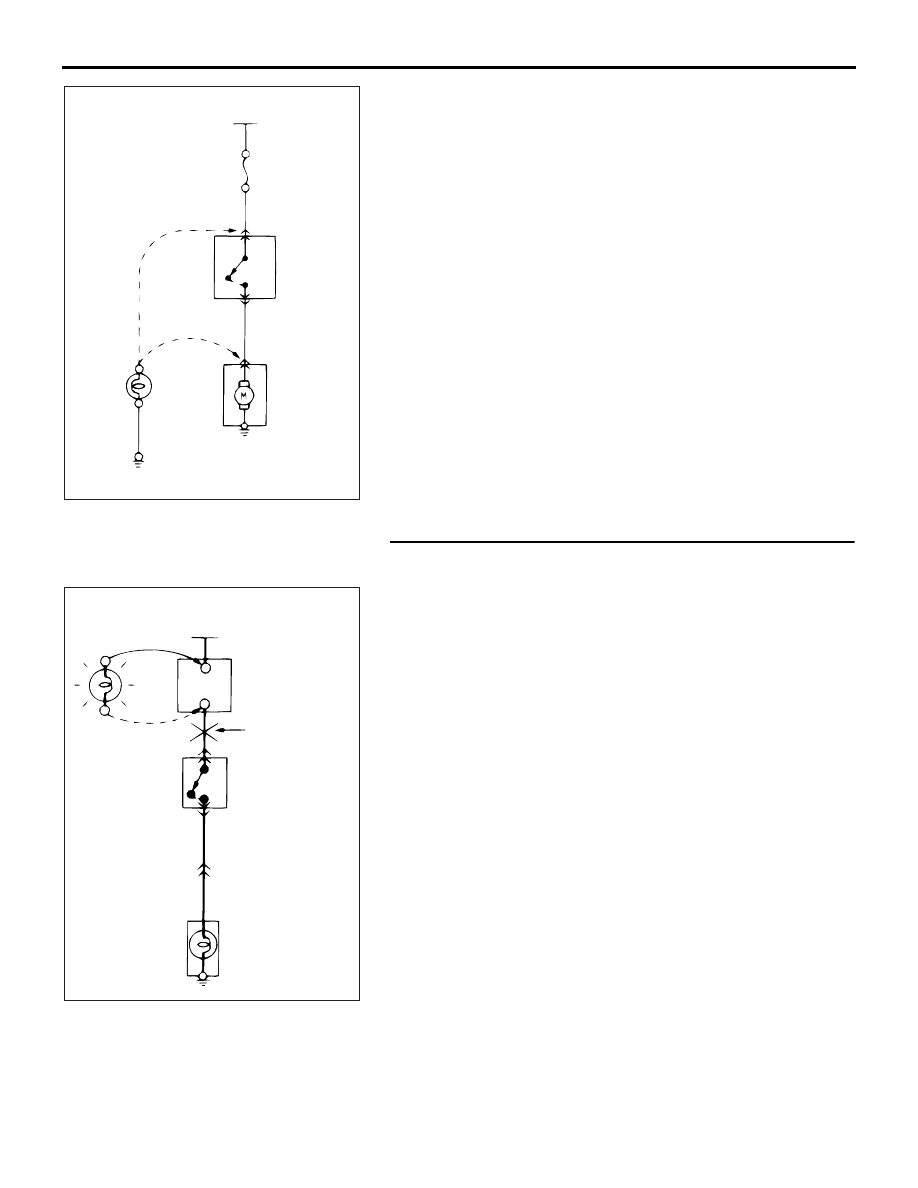
1. VOLTAGE CHECK
(1) Ground one lead wire of the test light. If a voltmeter is
used instead of the test light, ground the grounding side
lead wire.
(2) Connect the other lead wire of the test light to the power
side terminal of the switch connector. The test light
should come on or the voltmeter should indicate a
voltage.
(3) Then, connect the test light or voltmeter to the motor
connector. The test light should not come on, or the
voltmeter should indicate no voltage. When the switch is
turned ON in this state, the test light should come on, or
the voltmeter should indicate a voltage, with the motor
starting to run.
(4) The circuit illustrated here is normal. If there is any
problem, such as the motor failing to run, check voltages
beginning at the connector nearest to the motor until the
faulty part is identified.
2. SHORT-CIRCUIT CHECK
Because the fuse has blown, it is probable that there is a
short circuit. Follow the procedures below to narrow down
the short-circuit location.
STEP 1. Remove the blown fuse and connect the test light
across the fuse terminals (Circuit switch: OFF).
Q: Does the test light illuminate?
YES : Short-circuit exists between the fuse block and the
switch. Diagnose the harness between the fuse block
and the switch.
NO : Go to Step 2.
ACX00956AB
POWER SUPPLY
FUSE
SWITCH
MOTOR
(3)
ON (2)
OFF
(1)
TEST LIGHT
(OR
VOLTMETER)
ACX00957AB
POWER SUPPLY
SWITCH
OFF
ILLUMINATION
LIGHT
TEST
LIGHT
FUSE BLOCK
(REMOVE
THE FUSE)
SHORT-CIRCUIT
LOCATION