Mitsubishi 380. Manual - part 217
COMPRESSOR ASSEMBLY AND DRIVE BELT
HEATER, AIR CONDITIONING AND VENTILATION
55-164
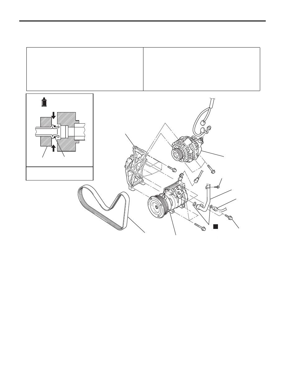
COMPRESSOR ASSEMBLY AND DRIVE BELT
REMOVAL AND INSTALLATION
M1552004100289
Pre-removal Operation
• Refrigerant Discharging (Refer to
• Front Bumper Under Cover (Refer to GROUP 51, FRONT
• Front Under Cover RH (Refer to GROUP 51, UNDER
).
Post-installation Operation
• Drive Belt Tension Adjustment (Refer to GROUP 00,
Maintenance Service
− Drive Belt
• Refrigerant Charging (Refer to
).
• Front Bumper Under Cover (Refer to GROUP 51, FRONT
BUMPER
• Front Under Cover RH (Refer to GROUP 51, UNDER
).
25DB139A
N
1
2
3
4
5
6
1, 2
3
A/C compressor oil:
ND Oil 8
-Pipe coupling
7
25 ± 4 N·m
18 ± 3 fi-lb
<3.8 L ENGINE>
12 ± 2 N·m
102 ± 22 in-lb
REMOVAL STEPS
<<A>>
>>A<<
1.
FLEXIBLE SUCTION HOSE
CONNECTION
<<A>>
2.
FLEXIBLE DISCHARGE HOSE
CONNECTION
3.
O-RING
4.
DRIVE BELT
<<B>>
>>B<<
5.
A/C COMPRESSOR
6.
ALTERNATOR
7.
A/C COMPRESSOR BRACKET
REMOVAL STEPS (Continued)