Mitsubishi 380. Manual - part 212
ON-VEHICLE SERVICE
HEATER, AIR CONDITIONING AND VENTILATION
55-144
REFRIGERANT LEAK INSPECTION PROCEDURE
M1552001500299
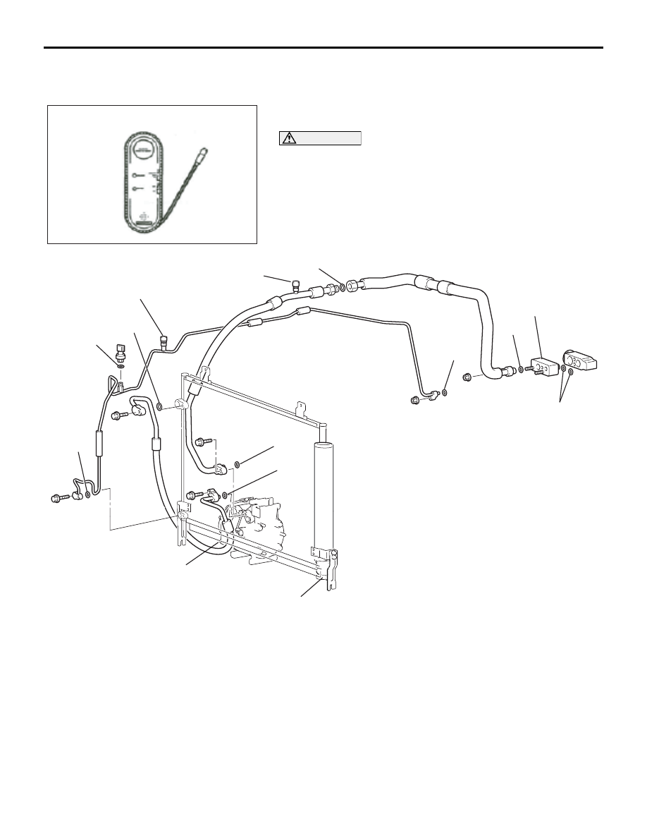
LEAK INSPECTION
1. Check for leakage using Special Tool at the following loca-
tions.
CAUTION
Good ventilation is necessary during the leak inspection. If
the surrounding air is contaminated with refrigerant gas,
the inspection readings will not be accurate.
25DB164A
ELECTRONIC LEAK DETECTOR
25DB163A
1
10
8
3
2
9
12
6
4
5
11
9
7
13
LEAK CHECK LOCATION
1.
SUCTION HOSE TO TX VALVE
2.
LIQUID TUBE TO TX VALVE
3.
SUCTION HOSE JOINT
4.
LOW PRESSURE SERVICE
VALVE
5.
HIGH PRESSURE SERVICE
VALVE
6.
CONDENSER-DISCHARGE
HOSE JOINT
7.
PRESSURE SENSOR
8.
CONDENSER-LIQUID TUBE
JOINT
9.
COMPRESSOR-SUCTION HOSE
JOINT
10. COMPRESSOR-DISCHARGE
HOSE JOINT
11. UNDER COMPRESSOR CLUTCH
12. AROUND MODULATOR CAP
13. TX VALVE TO EVAPORATOR
JOINT
LEAK CHECK LOCATION