Mitsubishi 380. Manual - part 203


  Index      Mitsubishi     Mitsubishi 380 - service repair manual 2005 year


Search            


Content   ..  201  202  203  204   ..


Mitsubishi 380. Manual - part 203


AUTO A/C DIAGNOSIS

HEATER, AIR CONDITIONING AND VENTILATION

55-108

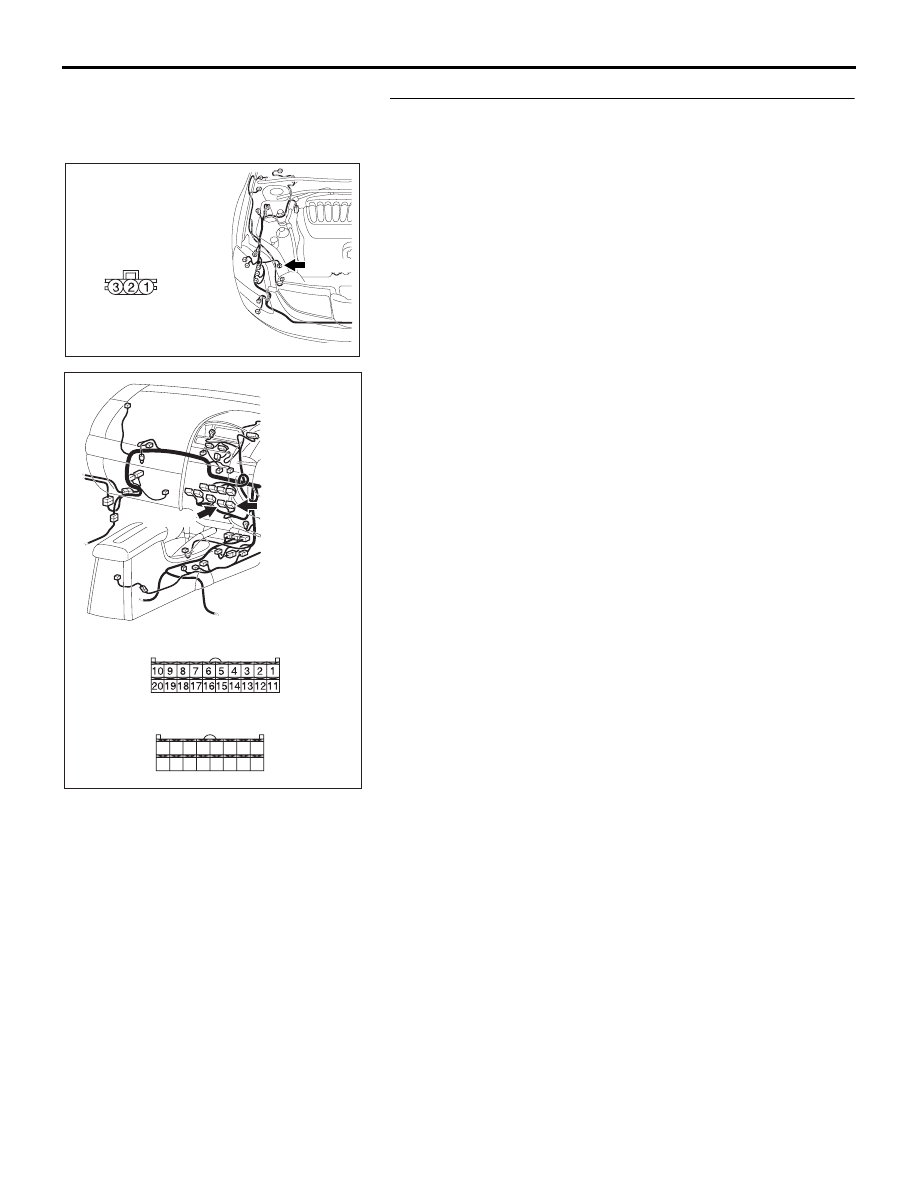
STEP 5. Check A/C-ECU C-15 and C-16 for loose, corroded 
or damaged terminals, or terminals pushed back in the 
connector.
Q: Are A/C-ECU C-15 and C-16 in good condition?

YES : Go to Step 6.
NO :  Repair or replace the connector. Refer to GROUP 

00E, Harness Connector Inspection 

P.00E-2

. Check 

that the air conditioning works normally. 

AC305206

CONNECTOR: A-30

AY

HARNESS SIDE

A-30 (B)

25DB070A

CONNECTORS: C-15, C-16

C-16 (B)

HARNESS SIDE

C-16

C-15

C-15 (B)

HARNESS SIDE

21

22

23

24

25

26

27

28

29

30

31

32

33

34

35

36

AUTO A/C DIAGNOSIS

HEATER, AIR CONDITIONING AND VENTILATION

55-109

STEP 6. Check the wiring harness between A/C-ECU 
connector C-15 (terminal 12), C-16 (terminals 34 and 26) 
and A/C pressure sensor connector A-30 (terminals 3, 1 
and 2).
Q: Is the wiring harness between A/C-ECU connector C-15 

(terminal 12), C-16 (terminals 34 and 26) and A/C 
pressure sensor connector A-30 (terminals 3, 1 and 2) in 
good condition?
YES : 
Repair the A/C-ECU. Check that the air conditioning 

works normally. 

NO :  Repair the wiring harness. Check that the air 

conditioning works normally. 

STEP 7. Check the refrigerant level.
Use the refrigerant recovery station to remove all of the refrig-
erant, and then calculate the amount of the refrigerant and 
charge it.

Q: Is the refrigerant level correct?

YES : Replace the A/C-ECU.Check that the air conditioning 

works normally. 

NO :  Correct the refrigerant level (Refer to On-vehicle 

Service

P.55-144

). Check that the air conditioning 

works normally. 

AC305206

CONNECTOR: A-30

AY

HARNESS SIDE

A-30 (B)

25DB070A

CONNECTORS: C-15, C-16

C-16 (B)

HARNESS SIDE

C-16

C-15

C-15 (B)

HARNESS SIDE

21

22

23

24

25

26

27

28

29

30

31

32

33

34

35

36

AUTO A/C DIAGNOSIS

HEATER, AIR CONDITIONING AND VENTILATION

55-110

INSPECTION PROCEDURE 8: Defogger Function Does Not Operate.

.

TECHNICAL DESCRIPTION (COMMENT)

If the defogger does not operate when the defogger 
switch is turned on, the defogger relay system may 
be defective.

.

TROUBLESHOOTING HINTS

• Malfunction of the A/C-ECU

• Malfunction of the defogger relay

• Damaged harness wires or connectors

• Refer to component locations GROUP-

70

• Refer to configuration diagrams GROUP-

80

• Refer to circuit diagrams GROUP-

90

DIAGNOSIS

Required Special Tool:

• MB991223: Test Harness Set

STEP 1. Check the A/C and outside/inside air selection 
damper control motor operation.

Q: Do the A/C and outside/inside air selection damper 

control motor work normally?
YES : 
Go to Step 2.
NO :  Refer to Inspection procedure 10, "Malfunction of the 

A/C-ECU power supply system

P.55-122

."

25DB122A

C-15 (B)

CONNECTOR: C-15

25DB123A

JUNCTION BLOCK 

(FRONT VIEW) 

C-204

C-211

C-215

C-201

C-216 (B)

CONNECTORS: C-201, C-204, C-211

C-215, C-216

25DB150A

CONNECTOR: C-31

25DB152A

CONNECTORS: D-11

D-11

AUTO A/C DIAGNOSIS

HEATER, AIR CONDITIONING AND VENTILATION

55-111

STEP 2. Check defogger relay connector C-201 for loose, 
corroded or damaged terminals, or terminals pushed back 
in the connector.
Q: Is defogger relay connector C-201 in good condition?

YES : Go to Step 3.
NO :  Repair or replace the connector. Refer to GROUP 

00E, Harness Connector Inspection 

P.00E-2

. The 

defogger system should work normally.

STEP 3. Check the defogger relay continuity.
Follow the table below to check the defogger relay for continu-
ity.

Q: Is the defogger relay in good condition?

YES : Go to Step 4.
NO :  Replace the defogger relay. The defogger system 

should work normally.

25DB125A

CONNECTOR: C-201

JUNCTION BLOCK SIDE

JUNCTION BLOCK 

(FRONT VIEW)

BATTERY VOLTAGE

CONNECT 
TESTER 
BETWEEN

SPECIFIED 
CONDITION

Not applied

− 5

Open Circuit

• Connect terminal 1 

to the positive 
battery terminal

• Connect terminal 3 

to the negative 
battery terminal

− 5

Less than 2 ohms

25DB126A

4
5

1 2 3

5

1

4

3

DEFOGGER RELAY


Content   ..  201  202  203  204   ..