Mitsubishi 380. Manual - part 197


  Index      Mitsubishi     Mitsubishi 380 - service repair manual 2005 year


Search            


Content   ..  195  196  197  198   ..


Mitsubishi 380. Manual - part 197


AUTO A/C DIAGNOSIS

HEATER, AIR CONDITIONING AND VENTILATION

55-84

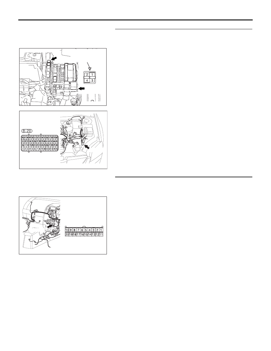
STEP 14. Check the wiring harness between powertrain 
control module connector B-20 (terminal 6) and A/C 
compressor clutch relay connector B-18X (terminal 3).
Q: Is the wiring harness between powertrain control 

module connector B-20 (terminal 6) and A/C 
compressor clutch relay connector B-18X (terminal 3) in 
good condition?
YES : 
It can be assumed that this malfunction is intermittent. 

Refer to GROUP 00, How to Use 
Troubleshooting/Inspection Service Points 

− How to 

Cope with Intermittent Malfunctions 

P.00-14

.

NO :  Repair the wiring harness. Check that the air 

conditioning works normally.

STEP 15. Check A/C-ECU connector C-15 for loose, 
corroded or damaged terminals, or terminals pushed back 
in the connector.
Q:  Is A/C-ECU connector C-15 in good condition?

YES : Go to Step 16.
NO :  Repair or replace the connector. Refer to GROUP 

00E, Harness Connector Inspection 

P.00E-2

. Check 

that the air conditioning works normally.

AC305977AJ

CONNECTOR: B-18X

RELAY BOX SIDE

FRONT OF 
VEHICLE

JUNCTION BLOCK 

TRIANGLE MARK

25DB148A

B-20

CONNECTOR: B-20

25DB092A

C-15

CONNECTOR: C-15

HARNESS SIDE

C-15

AUTO A/C DIAGNOSIS

HEATER, AIR CONDITIONING AND VENTILATION

55-85

STEP 16. Measure the voltage at A/C-ECU connector C-15. 
(1) Disconnect A/C-ECU connector C-15 and measure the 

voltage at the relay box side.

(2) Disconnect powertrain control module connector B-20 and 

ground harness side terminal No.6.

(3) Turn the ignition switch to the "ON" position.

(4) Measure the voltage between A/C-ECU connector C-15 

terminal No.10 and ground.

• The measured value should be approximately 12 volts 

(battery positive voltage).

Q: Does the measured voltage correspond with this range?

YES : Go to Step 18.
NO :   Go to Step 17.

25DB092A

C-15

CONNECTOR: C-15

HARNESS SIDE

C-15

25DB148A

B-20

CONNECTOR: B-20

25DB149A

CONNECTOR 

B-20 

AC209365HI

CONNECTOR C-15 
(HARNESS SIDE)

AUTO A/C DIAGNOSIS

HEATER, AIR CONDITIONING AND VENTILATION

55-86

STEP 17. Check the wiring harness between A/C 
compressor clutch relay connector B-18X (terminal 4) and 
A/C-ECU connector C-15 (terminal 10).

NOTE: Also check intermediate connectors A-13 and C-23 for 
loose, corroded, or damaged terminals, or terminals pushed 
back in the connector. If intermediate connector A-13 or C-23 is 
damaged, repair or replace the connector as described in 
GROUP 00E, Harness Connector Inspection 

P.00E-2

.

Q: Is the wiring harness between A/C compressor clutch 

relay connector B-18X (terminal 4) and A/C-ECU 
connector C-15 (terminal 10) in good condition?
YES : 
It can be assumed that this malfunction is intermittent. 

Refer to GROUP 00, How to Use 
Troubleshooting/Inspection Service Points 

− How to 

Cope with Intermittent Malfunctions 

P.00-14

.

NO :  Repair the wiring harness. Check that the air 

conditioning works normally.

AC305977AJ

CONNECTOR: B-18X

RELAY BOX SIDE

FRONT OF 
VEHICLE

JUNCTION BLOCK 

TRIANGLE MARK

25DB105A

C-15 (B)

C-23

C-15

HARNESS SIDE

C-23

CONNECTORS: C-15, C-23

AC305210

A-13 (GR)

AR

CONNECTOR: A-13

AUTO A/C DIAGNOSIS

HEATER, AIR CONDITIONING AND VENTILATION

55-87

STEP 18. Check the air conditioning compressor clutch 
operation.
Connect the compressor connector terminal to the battery posi-
tive (+) terminal and ground the battery’s negative (-) terminal 
to the compressor unit. At that time, the air conditioning com-
pressor clutch should make a definite operating sound.

Q: Can the sound (click) of the air conditioning 

compressor clutch operation be heard?
YES : 
Go to Step 19.
NO :  Replace the compressor magnet clutch. Check that 

the air conditioning works normally. 

STEP 19. Check the air thermo sensor.
Measure the resistance between connector terminals 1 and 2 
under at least two different temperatures. The resistance val-
ues should generally match those in the graph. 

NOTE: The temperature at the check should not exceed the 
range in the graph. 

Q: Is the air thermo sensor in good condition?

YES : Go to Step 20.
NO :  Replace the air thermo sensor. Check that the air 

conditioning works normally.

STEP 20. Check the ambient air temperature sensor.
Measure the resistance between the sensor terminals under at 
least two temperatures. The resistance values should meet the 
values shown.

NOTE: The temperature should be within the shown range.

Q: Is the ambient air temperature sensor in good 

condition?
YES : 
Go to Step 22.
NO :  Replace the ambient air temperature sensor. Check 

that the air conditioning works normally.

AC206292AB

A/C COMPRESSOR 
CLUTCH 
CONNECTOR

AC001043

RESISTANCE kΩ

8

6

4

2

0

-10

0

 10

 20

 30

   40

TEMPERATURE ˚C(˚F)

AB

(14)

(32)

(50)

(86) (104)

(68)

AC209942AB

REGISTANCE 
kΩ

10

20

30

40

0

0

20

(32) (68)

TEMPERATURE ˚C (˚F)

40

(104)

60

(140)

-20

(-4)

-30

(-22)


Content   ..  195  196  197  198   ..