Mitsubishi 380. Manual - part 188


  Index      Mitsubishi     Mitsubishi 380 - service repair manual 2005 year


Search            


Content   ..  186  187  188  189   ..


Mitsubishi 380. Manual - part 188


AUTO A/C DIAGNOSIS

HEATER, AIR CONDITIONING AND VENTILATION

55-48

DTC B1065:  Mode Selection Damper Control Motor and Potentiometer

.

DTC SET CONDITION

• If the air mixing damper control motor does not 

work normally, DTC B1065 will be set.

.

TECHNICAL DESCRIPTION (COMMENT)

Current trouble

• The A/C-ECU, the mode selection damper con-

trol motor and potentiometer, or connector(s) or 
wiring between them may be defective.

Past trouble

• If DTC B1065 is stored as a past trouble, carry 

out diagnosis with particular emphasis on wiring 
and connector(s) between the A/C-ECU and the 
mode selection damper control motor and poten-
tiometer. If the connectors and wiring are normal, 
and obviously the ECU is the cause of the trou-
ble, replace the ECU. If in doubt, do not replace 
the ECU.

TROUBLESHOOTING HINT

• Malfunction of connector.

• Malfunction of the harness.

• Malfunction of the mode selection damper control 

motor and potentiometer.

• Malfunction of the A/C-ECU.

• Refer to component locations GROUP-

70

• Refer to configuration diagrams GROUP-

80

• Refer to circuit diagrams GROUP-

90

25DB070A

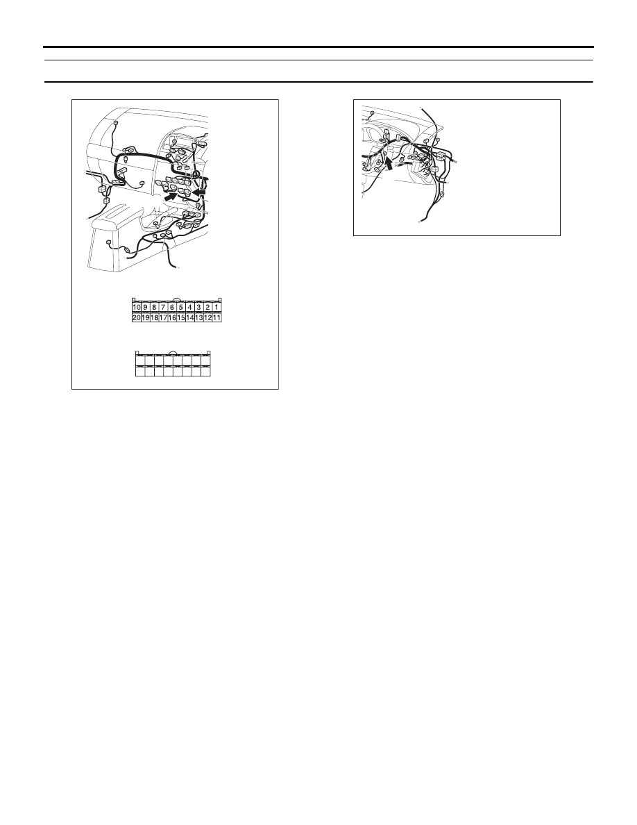
CONNECTORS: C-15, C-16

C-16 (B)

HARNESS SIDE

C-16

C-15

C-15 (B)

HARNESS SIDE

21

22

23

24

25

26

27

28

29

30

31

32

33

34

35

36

25DB091A

C-102

CONNECTOR: C-102

AUTO A/C DIAGNOSIS

HEATER, AIR CONDITIONING AND VENTILATION

55-49

DIAGNOSIS

Required Special Tool:

•  : Diagnostic Tool (MUT-III Sub Assembly)

• MB991824: Vehicle Communication Interface (V.C.I.)

• MB991827: MUT-III USB Cable

• MB991910: MUT-III Main Harness A (Vehicles with CAN 

communication system)

STEP 1. Using diagnostic tool , diagnose the CAN bus line.
Use diagnostic tool  to diagnose the CAN bus lines.
(1) Connect diagnostic tool  to the data link connector.
(2) Turn the ignition switch to "ON" position.
(3) Diagnose the CAN bus line.

Q: Is the check result satisfactory?

YES : Go to Step 2.
NO :  Repair the CAN bus lines. (Refer to GROUP 54C, 

Diagnosis-Can Bus Diagnostic Chart 

P.54C-405

). 

Then go to Step 7.

STEP 2. Recheck for diagnostic trouble code.
Recheck if the DTC is set.
(1) Erase the DTC.
(2) Turn the ignition switch to "ON" position.
(3) Check if the DTC is set.

Q: Is the check result satisfactory?

YES : It can be assumed that this malfunction is intermittent. 

Refer to GROUP 00, How to Use 
Troubleshooting/Inspection Service Points 

− How to 

Cope with Intermittent Malfunctions 

P.00-14

.

NO :  Go to Step 3. 

00DB076A

MB991910

DATA LINK

CONNECTOR

MB991824

MB991827

AUTO A/C DIAGNOSIS

HEATER, AIR CONDITIONING AND VENTILATION

55-50

STEP 3. Using diagnostic tool , check actuator test item 67, 
68, 69, 70, 71: Air outlet c/o dumper.

CAUTION

To prevent damage to diagnostic tool , always turn the 
ignition switch to the "LOCK" (OFF) position before con-
necting or disconnecting diagnostic tool .
(1) Connect diagnostic tool  to the data link connector.
(2) Start the engine.
(3) Use diagnostic tool  to run the actuator test.

Item 67: air mix damper motor (Bi LEVEL position)
Item 68: air mix damper motor (DEF position)
Item 69: air mix damper motor (DEF/FOOT position)
Item 70: air mix damper motor (FACE position)
Item 71: air mix damper motor (FOOT position)

• Check that the mode selection damper control motor 

operates.

(4) Turn the ignition switch to the "LOCK" (OFF) position.

Q: Is the sensor within the specified range?

YES : Replace the A/C-ECU. Then go to Step 7.
NO :  Go to Step 4.

STEP 4. Check A/C-ECU connector C-15 and mode 
selection damper control motor and potentiometer 
connector C-102 for loose, corroded or damaged 
terminals, or terminals pushed back in the connector.
Q: Are A/C-ECU connector C-15 and mode selection 

damper control motor and potentiometer connector 
C-102 in good condition?
YES : 
Go to Step 5.
NO :  Repair or replace the connector. Refer to GROUP 

00E, Harness Connector Inspection 

P.00E-2

. Then g

to Step 7.

00DB076A

MB991910

DATA LINK

CONNECTOR

MB991824

MB991827

25DB092A

C-15

CONNECTOR: C-15

HARNESS SIDE

C-15

25DB088A

C-102

HARNESS SIDE

CONNECTOR: C-102

AUTO A/C DIAGNOSIS

HEATER, AIR CONDITIONING AND VENTILATION

55-51

STEP 5. Check the wiring harness between A/C-ECU 
connector C-15 (terminals 11 and 4) and mode selection 
damper control motor and potentiometer connector C-102 
(terminals 1 and 2).
Q: Are the wiring harnesses between A/C-ECU connector 

C-15 (terminals 11 and 4) and mode selection damper 
control motor and potentiometer connector C-102 
(terminals 1 and 2) in good condition?
YES : 
Go to Step 6.
NO :  Repair the wiring harness. Then go to Step 7.

25DB092A

C-15

CONNECTOR: C-15

HARNESS SIDE

C-15

25DB088A

C-102

HARNESS SIDE

CONNECTOR: C-102


Content   ..  186  187  188  189   ..