Mitsubishi 380. Manual - part 176


  Index      Mitsubishi     Mitsubishi 380 - service repair manual 2005 year


Search            


Content   ..  174  175  176  177   ..


Mitsubishi 380. Manual - part 176


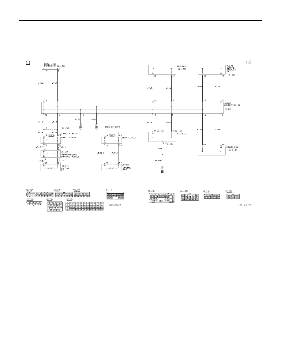
CONTROLLER AREA NETWORK (CAN)

CIRCUIT DIAGRAMS

90-124

HEATER, AIR CONDITIONING AND VENTILATION

55-1

GROUP 55

HEATER, AIR 

CONDITIONING AND 

VENTILATION

CONTENTS

GENERAL DESCRIPTION. . . . . . . . .

55-3

AUTO A/C DIAGNOSIS . . . . . . . . . . .

55-5

INTRODUCTION. . . . . . . . . . . . . . . . . . . . . 

55-5

AUTOMATIC AIR CONDITIONING 
TROUBLESHOOTING STRATEGY . . . . . . 

55-5

DIAGNOSTIC FUNCTION  . . . . . . . . . . . . . 

55-5

DIAGNOSTIC TROUBLE CODE CHART   . 

55-9

DIAGNOSTIC TROUBLE CODE 
PROCEDURES. . . . . . . . . . . . . . . . . . . . . . 

55-10

SYMPTOM CHART  . . . . . . . . . . . . . . . . . . 

55-68

SYMPTOM PROCEDURES . . . . . . . . . . . . 

55-69

DATA LIST REFERENCE TABLE  . . . . . . . 

55-133

ACTUATOR TEST REFERENCE . . . . . . . . 

55-136

CHECK AT A/C-ECU TERMINAL . . . . . . . . 

55-137

SPECIAL TOOLS. . . . . . . . . . . . . . . .

55-139

ON-VEHICLE SERVICE. . . . . . . . . . .

55-141

REFRIGERANT LEVEL TEST  . . . . . . . . . . 

55-141

A/C COMPRESSOR CLUTCH TEST . . . . . 

55-141

SIMPLE INSPECTION OF THE A/C 
PRESSURE SENSOR  . . . . . . . . . . . . . . . . 

55-141

COMPRESSOR DRIVE BELT 
ADJUSTMENT  . . . . . . . . . . . . . . . . . . . . . . 

55-142

CHARGING. . . . . . . . . . . . . . . . . . . . . . . . . 

55-142

PERFORMANCE TEST  . . . . . . . . . . . . . . . 

55-143

REFRIGERANT LEAK INSPECTION 
PROCEDURE . . . . . . . . . . . . . . . . . . . . . . . 

55-144

A/C NOISE TEST  . . . . . . . . . . . . . . . . . . . . 

55-146

POWER RELAY CHECK. . . . . . . . . . . . . . . 

55-148

IDLE-UP OPERATION CHECK. . . . . . . . . . 

55-149

HEATER CONTROL ASSEMBLY AND 
A/C SWITCH . . . . . . . . . . . . . . . . . . . .

55-150

REMOVAL AND INSTALLATION  . . . . . . . . 

55-150

HEATER UNIT, HEATER CORE, 
BLOWER ASSEMBLY AND 
EVAPORATOR UNIT . . . . . . . . . . . . .

55-151

REMOVAL AND INSTALLATION  . . . . . . . . 

55-151

REMOVAL AND INSTALLATION  . . . . . . . . 

55-153

DISASSEMBLY AND ASSEMBLY  . . . . . . . 

55-154

INSPECTION. . . . . . . . . . . . . . . . . . . . . . . . 

55-155

BLOWER ASSEMBLY DISASSEMBLY 
AND ASSEMBLY. . . . . . . . . . . . . . . . . . . . . 

55-156

MOTORS AND TRANSISTOR . . . . . .

55-157

REMOVAL AND INSTALLATION  . . . . . . . . 

55-157

INSPECTION. . . . . . . . . . . . . . . . . . . . . . . . 

55-158

SENSORS . . . . . . . . . . . . . . . . . . . . . .

55-160

REMOVAL AND INSTALLATION  . . . . . . . . 

55-160

INSPECTION. . . . . . . . . . . . . . . . . . . . . . . . 

55-161

Continued on next page

HOME

HEATER, AIR CONDITIONING AND VENTILATION

55-2

AMBIENT TEMPERATURE 
SENSOR. . . . . . . . . . . . . . . . . . . . . . .

55-162

REMOVAL AND INSTALLATION . . . . . . . . 

55-162

INSPECTION  . . . . . . . . . . . . . . . . . . . . . . . 

55-163

COMPRESSOR ASSEMBLY AND 
DRIVE BELT  . . . . . . . . . . . . . . . . . . .

55-164

REMOVAL AND INSTALLATION . . . . . . . . 

55-164

INSPECTION  . . . . . . . . . . . . . . . . . . . . . . . 

55-166

AIR GAP CHECK  . . . . . . . . . . . . . . . . . . . . 

55-166

CONDENSER AND CONDENSER 
FAN  . . . . . . . . . . . . . . . . . . . . . . . . . .

55-167

REMOVAL AND INSTALLATION . . . . . . . . 

55-167

INSPECTION  . . . . . . . . . . . . . . . . . . . . . . . 

55-168

DRYER REPLACEMENT . . . . . . . . . . . . . . 

55-168

REFRIGERANT LINE . . . . . . . . . . . . .

55-170

REMOVAL AND INSTALLATION  . . . . . . . . 

55-170

O-RING AND PIPE INSTALLATION . . . . . . 

55-172

DUCTS  . . . . . . . . . . . . . . . . . . . . . . . .

55-175

REMOVAL AND INSTALLATION  . . . . . . . . 

55-175

VENTILATORS . . . . . . . . . . . . . . . . . .

55-177

REMOVAL AND INSTALLATION  . . . . . . . . 

55-177

SPECIFICATIONS  . . . . . . . . . . . . . . .

55-178

FASTENER TIGHTENING 
SPECIFICATIONS. . . . . . . . . . . . . . . . . . . . 

55-178

GENERAL SPECIFICATIONS  . . . . . . . . . . 

55-178

SERVICE SPECIFICATIONS  . . . . . . . . . . . 

55-178

LUBRICANTS  . . . . . . . . . . . . . . . . . . . . . . . 

55-178

GENERAL DESCRIPTION

HEATER, AIR CONDITIONING AND VENTILATION

55-3

GENERAL DESCRIPTION

M1552000100351

The heater and cooling units are combined in a sin-
gle unit, which, with the mode film damper and flow 
rate control valve in the heater unit, reduces ventila-
tion resistance, increases fan power, and decreases 
noise. 

SAFETY PRECAUTIONS

WARNING

Wear safety goggles and gloves when servic-
ing the refrigeration system to prevent 
severe damage to eyes and hands.

Because R-134a refrigerant is a hydro fluorocarbon 
(HFC) which contains hydrogen atoms in place of 
chlorine atoms, it will not cause damage to the ozone 
layer.
Ozone filters out harmful radiation from the sun. To 
assist in protecting the ozone layer, Mitsubishi 
Motors Corporation recommends an R-134a refriger-
ant recycling device.
Refrigerant R-134a is transparent and colorless in 
both the liquid and vapor state. Since it has a boiling 
point of 

−29.8°C (−21.64°F) at atmospheric pressure, 

it will be a vapor at all normal temperatures and pres-
sures. The vapor is heavier than air, non-flammable, 
and non-explosive. The following precautions must 
be observed when handling R-134a.

WARNING

Do not heat R-134a above 40

°C (104.0°F) or it 

may catch fire and explode.

R-134a evaporates so rapidly at normal atmospheric 
pressures and temperatures that it tends to freeze 
anything it contacts. For this reason, extreme care 
must be taken to prevent any liquid refrigerant from 
contacting the skin and especially the eyes. Always 
wear safety goggles when servicing the refrigeration 
part of the A/C system. Keep a bottle of sterile min-
eral oil handy when working on the refrigeration sys-
tem.

1. If any liquid refrigerant gets into your eyes, use a 

few drops of mineral oil to wash them out. R-134a 
is rapidly absorbed by the oil.

2. Next, splash your eyes with plenty of cold water.

3. Call your doctor immediately even if irritation has 

ceased.

CAUTION

Keep R-134a containers upright when charging 
the system.
In most instances, moderate heat is required to bring 
the pressure of the refrigerant in its container above 
the pressure of the system when charging or adding 
refrigerant.
A bucket or large pan of hot water not over 40

°C 

(104.0

°F) is all the heat required for this purpose. Do 

not heat the refrigerant container with a blow torch or 
any other means that would raise temperature and 
pressure above this temperature. Do not weld or 
steam-clean on or near the system components or 
refrigerant lines.

WARNING

A leak detector for R-134a should be used to 
check for refrigerant gas leaks.

CAUTION

Do not allow liquid refrigerant to touch bright 
metal or it will be stained.
When metering R-134a into the refrigeration system, 
keep the supply tank or cans in an upright position. If 
the refrigerant container is on its side or upside 
down, liquid refrigerant will enter the system and 
damage the compressor.
Refrigerant will tarnish bright metal and chrome sur-
faces, and in combination with moisture can severely 
corrode all metal surfaces.

ITEM

SPECIFICATION

Heater control assembly

Dial type

Compressor

10S17

Compressor Model

Swashplate type

Refrigerant and quantity (g) 

R-134a (HFC-134a), 435 

− 475


Content   ..  174  175  176  177   ..