Mitsubishi 380. Manual - part 109


  Index      Mitsubishi     Mitsubishi 380 - service repair manual 2005 year


Search            


Content   ..  107  108  109  110   ..


Mitsubishi 380. Manual - part 109


INPUT SIGNAL PROCEDURES

SIMPLIFIED WIRING SYSTEM (SWS)

54B-433

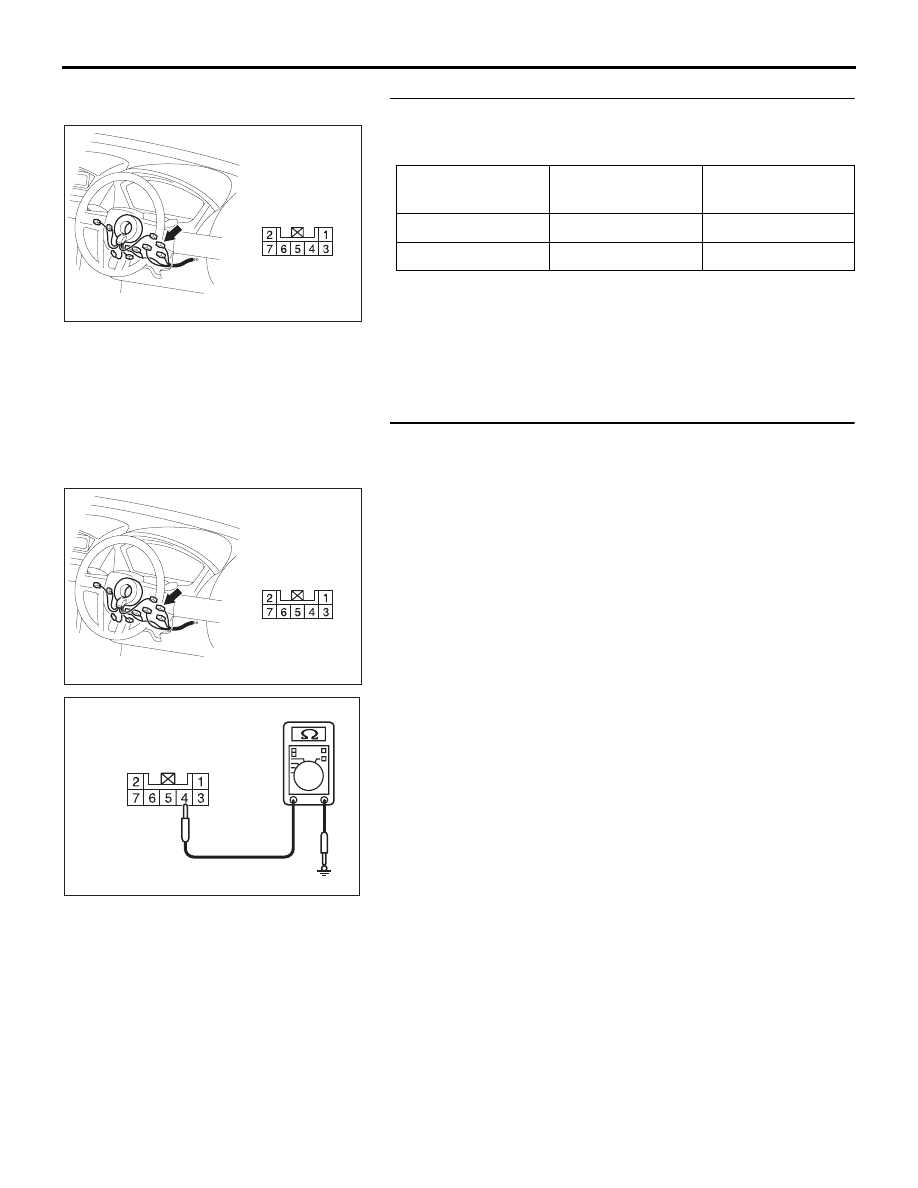
STEP 2. Check the key reminder switch.
Disconnect key reminder switch connector C-310. Then check 
continuity between terminals.

Q: Is the key reminder switch in good condition?

YES : Go to Step 3.
NO :  Replace the key reminder switch. If the functions 

described in "CIRCUIT OPERATION" work normally, 
the input signal from the key reminder switch should 
be normal.

STEP 3. Check the ground circuit to the key reminder 
switch. Measure the resistance at key reminder switch 
connector C-310.
(1) Disconnect key reminder switch connector C-310 and 

measure the resistance available at the wiring harness side 
of the connector.

(2) Measure the resistance value between terminal 4 and 

ground.

• The resistance should be 2 ohms or less.

Q: Is the measured resistance 2 ohms or less?

YES : Go to Step 5.
NO :  Go to Step 4.

IGNITION KEY

TESTER 
CONNECTION

SPECIFIED 
CONDITION

Removed

− 6

Open circuit

Inserted

− 6

Less than 2 ohms

54DB004A

CONNECTOR: C-310

HARNESS SIDE

54DB004A

CONNECTOR: C-310

HARNESS SIDE

AC209364GZ

CONNECTOR C-310
(HARNESS SIDE)

INPUT SIGNAL PROCEDURES

SIMPLIFIED WIRING SYSTEM (SWS)

54B-434

STEP 4. Check the wiring harness between key reminder 
switch connector C-310 (terminal 4) and ground.
Q: Is the wiring harness between key reminder switch 

connector C-310 (terminal 4) and ground in good 
condition?
YES : 
No action is necessary and testing is complete.
NO :  The wiring harness may be damaged or the 

connector(s) may have loose, corroded or damaged 
terminals, or terminals pushed back in the connector. 
Repair the wiring harness as necessary. If the 
functions described in "CIRCUIT OPERATION" work 
normally, the input signal from the key reminder 
switch should be normal.

STEP 5. Check ETACS-ECU connector C-217 for loose, 
corroded or damaged terminals, or terminals pushed back 
in the connector.
Q: Is ETACS-ECU connector C-217 in good condition?

YES : Go to Step 6.
NO :  Repair or replace the damaged component(s). Refer 

to GROUP 00E, Harness Connector Inspection 

P.00E-2

. If the functions described in "CIRCUIT 

OPERATION" work normally, the input signal from the 
key reminder switch should be normal.

54DB004A

CONNECTOR: C-310

HARNESS SIDE

16DB307A

CONNECTOR: C-217

HARNESS SIDE

25

26

27

28

29

21

22

23

24

30

31

32

33

34

35

36

37

38

39

40

41

42

43

44

JUNCTION BLOCK

(REAR VIEW)

INPUT SIGNAL PROCEDURES

SIMPLIFIED WIRING SYSTEM (SWS)

54B-435

STEP 6. Check the wiring harness between key reminder 
switch connector C-310 (terminal 6) and ETACS-ECU 
connector C-217 (terminal 30).
Q: Is the wiring harness between key reminder switch 

connector C-310 (terminal 6) and ETACS-ECU connector 
C-217 (terminal 30) in good condition?
YES : 
Go to Step 7.
NO :  The wiring harness may be damaged or the 

connector(s) may have loose, corroded or damaged 
terminals, or terminals pushed back in the connector. 
Repair the wiring harness as necessary. If the 
functions described in "CIRCUIT OPERATION" work 
normally, the input signal from the key reminder 
switch should be normal.

STEP 7. Check for continuity between key reminder switch 
connector C-310 terminal 4 and each of the other terminals 
as well as terminal 6 and each of the other terminals.
(1) Disconnect key reminder switch connector C-310 and 

measure the resistance available at the equipment side of 
the connector. 

(2) Check for continuity between key reminder switch 

connector C-310 terminal 4 and each of the other terminals 
as well as terminal 6 and each of the other terminals.

Q: Does continuity exist between the terminals?

NO :  Replace the ETACS-ECU. If the functions described 

in "CIRCUIT OPERATION" work normally, the input 
signal from the key reminder switch should be normal.

YES : Replace the key reminder switch. If the functions 

described in "CIRCUIT OPERATION" work normally, 
the input signal from the key reminder switch should 
be normal.

16DB307A

CONNECTOR: C-217

HARNESS SIDE

25

26

27

28

29

21

22

23

24

30

31

32

33

34

35

36

37

38

39

40

41

42

43

44

JUNCTION BLOCK

(REAR VIEW)

54DB004A

CONNECTOR: C-310

HARNESS SIDE

16DB307A

CONNECTOR: C-217

HARNESS SIDE

25

26

27

28

29

21

22

23

24

30

31

32

33

34

35

36

37

38

39

40

41

42

43

44

JUNCTION BLOCK

(REAR VIEW)

INPUT SIGNAL PROCEDURES

SIMPLIFIED WIRING SYSTEM (SWS)

54B-436

INSPECTION PROCEDURE N-2: ETACS-ECU does not receive any signal from the hazard warning 
lamp switch.

.

CIRCUIT OPERATION

The ETACS-ECU operates the following functions or 
systems according to signal from the hazard warning 
lamp switch:

• Turn-signal lamp buzzer

• Hazard warning lamp

• Keyless entry system (registering the encrypted 

code)

.

TECHNICAL DESCRIPTION (COMMENT)

If the signal is not normal, the equipment or systems 
described in "CIRCUIT OPERATION" do not work 
normally.

.

TROUBLESHOOTING HINTS

• Refer to circuit diagrams GROUP-

90

• Refer to configuration diagrams GROUP-

80

• The hazard warning lamp switch may be defec-

tive

• The wiring harness or connectors may have 

loose, corroded, or damaged terminals, or termi-
nals pushed back in the connector

• The ETACS-ECU may be defective

DIAGNOSIS

Required Special Tool:

• MB991223: Harness Set

STEP 1. Check hazard warning lamp switch connector 
C-08 for loose, corroded or damaged terminals, or 
terminals pushed back in the connector.
Q: Is hazard warning lamp switch connector C-08 in good 

condition?
YES : 
Go to Step 2.
NO :  Repair or replace the damaged component(s). Refer 

to GROUP 00E, Harness Connector Inspection 

P.00E-2

. If the equipment described in "CIRCUIT 

OPERATION" work normally, the input signal from the 
hazard warning lamp switch should be normal.

16DB463A

CONNECTOR: C-08

HARNESS SIDE

54DB006A

CONNECTORS: C-218

JUNCTION BLOCK
(REAR VIEW)

C-218 (GR)

HARNESS SIDE

45

46

48 47

49

50
59

51
60

52

53
62

65

61

54
63

56

68

64

67 66

57

58

55

16DB463A

CONNECTOR: C-08

HARNESS SIDE


Content   ..  107  108  109  110   ..