Mitsubishi 380. Manual - part 96
SYMPTOM PROCEDURES
SIMPLIFIED WIRING SYSTEM (SWS)
54B-381
INSPECTION PROCEDURE K-4: Interior Light: The ignition key hole illumination lamp does not
illuminate or go out normally.
NOTE: This troubleshooting procedure requires the
use of diagnostic tool MB991958 and SWS monitor
kit MB991813. For details on how to use the SWS
monitor, refer to "How to connect SWS monitor
."
.
CIRCUIT OPERATION
• When the driver's door is opened with the ignition
switch at "ACC" position, the ETACS-ECU illumi-
nates the ignition key hole illumination lamp.
• The ignition key hole illumination lamp goes out
in 30 seconds after the driver's door is closed.
The ignition key hole illumination lamp remains
illuminated for 30 seconds after the ignition key is
pulled out.
• The ETACS-ECU operates the ignition key hole
illumination lamp according to the input signals
from the following switches:
• Ignition switch (IG1): OFF
• Key reminder switch: OFF
• Interior lamp loaded signal: ON
• Vehicle condition:
• Ignition switch: "LOCK" (OFF) or "ACC" posi-
tion
• Ignition key: Removed from the ignition key
cylinder
• Driver’s door: Opened or closed
.
TECHNICAL DESCRIPTION (COMMENT)
If the ignition key hole illumination lamp does not illu-
minate, the input circuits from the switches described
in "CIRCUIT OPERATION", the key reminder switch
(ignition key hole illumination lamp bulb) or the
ETACS-ECU may be defective.
.
TROUBLESHOOTING HINTS
• Refer to circuit diagrams GROUP-
• Refer to configuration diagrams GROUP-
• Trouble in input signal system
• The wiring harness or connectors may have
loose, corroded, or damaged terminals, or termi-
nals pushed back in the connector
• The ETACS-ECU may be defective
25DB113A
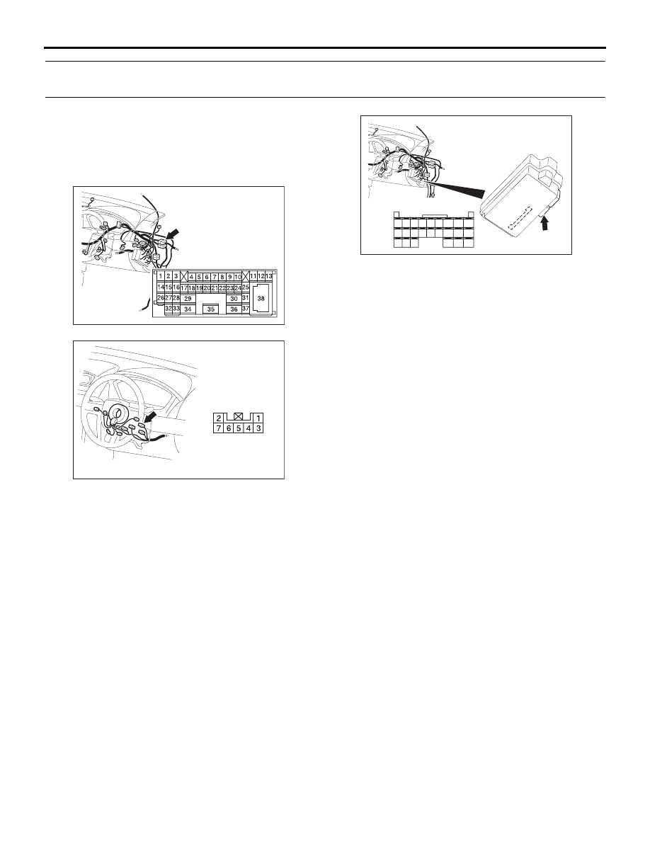
CONNECTOR: C-29
54DB006A
CONNECTORS: C-218
JUNCTION BLOCK
(REAR VIEW)
C-218 (GR)
HARNESS SIDE
45
46
48 47
49
50
59
51
60
52
53
62
65
61
54
63
56
68
64
67 66
57
58
55
54DB004A
CONNECTOR: C-310
HARNESS SIDE