Mitsubishi 380. Manual - part 81


  Index      Mitsubishi     Mitsubishi 380 - service repair manual 2005 year


Search            


Content   ..  79  80  81  82   ..


Mitsubishi 380. Manual - part 81


SYMPTOM PROCEDURES

SIMPLIFIED WIRING SYSTEM (SWS)

54B-321

STEP 10. Check the ground circuit to the ETACS-ECU. 
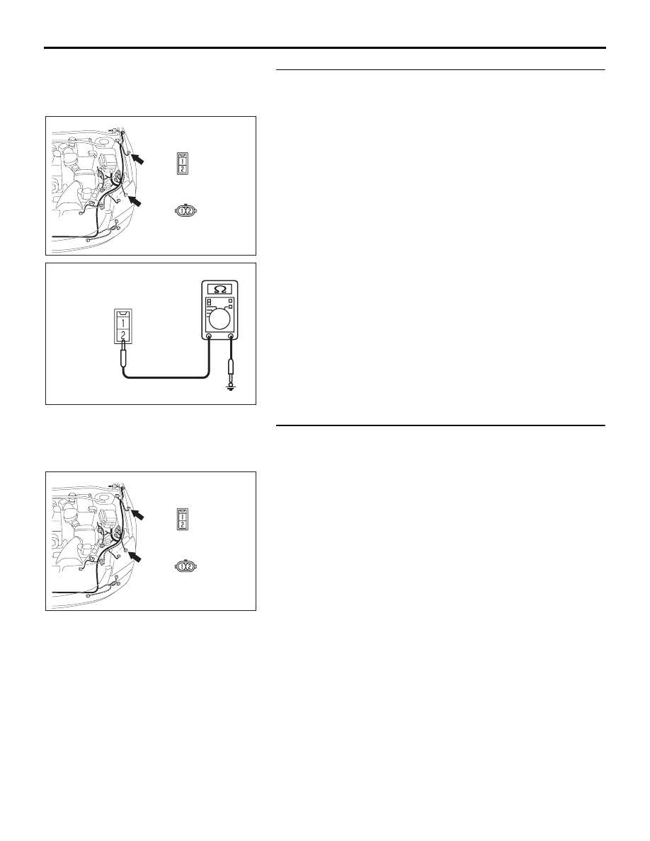
Measure the resistance at side turn-signal lamp (LH) 
connector A-17.
(1) Disconnect side turn-signal lamp (LH) connector A-17 and 

measure the resistance available at the wiring harness side 
of the connector.

(2) Measure the resistance value between terminal 2 and 

ground.

• The resistance should be 2 ohms or less.

Q: Is the measured resistance 2 ohms or less?

YES : Go to Step 12.
NO :  Go to Step 11.

STEP 11. Check the wiring harness between side 
turn-signal lamp (LH) connector A-17 (terminal 2) and 
ground.
Q: Is the wiring harness between side turn-signal lamp 

(LH) connector A-17 (terminal 2) and ground in good 
condition?
YES : 
Replace the side turn-signal lamp socket (LH). Verify 

that the turn-signal lamps illuminate normally.

NO :  The wiring harness may be damaged or the 

connector(s) may have loose, corroded or damaged 
terminals, or terminals pushed back in the connector. 
Repair the wiring harness as necessary. Verify that 
the turn-signal lamps illuminate normally.

16DB443A

CONNECTOR: A-18, A-17

A-18

A-17

16DB446A

CONNECTOR A-17

(HARNESS SIDE)

16DB443A

CONNECTOR: A-18, A-17

A-18

A-17

SYMPTOM PROCEDURES

SIMPLIFIED WIRING SYSTEM (SWS)

54B-322

STEP 12. Check ETACS-ECU connector C-219 for loose, 
corroded or damaged terminals, or terminals pushed back 
in the connector.
Q: Is ETACS-ECU connector C-219 in good condition?

YES : Go to Step 7.
NO :  Repair or replace the damaged component(s). Refer 

to GROUP 00E, Harness Connector Inspection 

P.00E-2

. Verify that the turn-signal lamps illuminate 

normally.

STEP 13. Check the wiring harness between side 
turn-signal lamp (LH) connector A-17 (terminal 1) and 
ETACS-ECU connector C-219 (terminal 14).

16DB327A

CONNECTOR: C-219

JUNCTION BLOCK

(REAR VIEW)

16DB443A

CONNECTOR: A-18, A-17

A-18

A-17

16DB327A

CONNECTOR: C-219

JUNCTION BLOCK

(REAR VIEW)

SYMPTOM PROCEDURES

SIMPLIFIED WIRING SYSTEM (SWS)

54B-323

NOTE: Also check junction block connector C-214 for loose, 
corroded, or damaged terminals, or terminals pushed back in 
the connector. If junction block connector C-214 is damaged, 
repair or replace the damaged component(s) as described in 
GROUP 00E, Harness Connector Inspection 

P.00E-2

.

Q: Is the wiring harness between side turn-signal lamp 

(LH) connector A-17 (terminal 1) and ETACS-ECU 
connector C-219 (terminal 14) in good condition?
YES : 
Replace the side turn-signal lamp socket (LH). Verify 

that the turn-signal lamps illuminate normally.

NO :  The wiring harness may be damaged or the 

connector(s) may have loose, corroded or damaged 
terminals, or terminals pushed back in the connector. 
Repair the wiring harness as necessary. Verify that 
the turn-signal lamps illuminate normally.

STEP 14. Check front combination lamp (RH) connector 
A-34 for loose, corroded or damaged terminals, or 
terminals pushed back in the connector.
Q: Is front combination lamp (RH) connector A-34 in good 

condition?
YES : 
Go to Step 15.
NO :  Repair or replace the damaged component(s). Refer 

to GROUP 00E, Harness Connector Inspection 

P.00E-2

. Verify that the turn-signal lamps illuminate 

normally.

STEP 15. Check the front turn-signal lamp bulb (RH).
(1) Remove the front turn-signal (RH) lamp bulb.
(2) Verify that the front turn-signal lamp bulb (RH) is not 

damaged or burned out.

Q: Is the front turn-signal (RH) lamp bulb in good 

condition?
YES : 
Go to Step 16.
NO :  Replace the front turn-signal (RH) lamp bulb. Verify 

that the turn-signal lamps illuminate normally.

16DB444A

CONNECTOR: A-34, A-35

A-34 

A-35

SYMPTOM PROCEDURES

SIMPLIFIED WIRING SYSTEM (SWS)

54B-324

STEP 16. Check the ground circuit to the front 
combination lamp (RH). Measure the resistance at front 
combination lamp (RH) connector A-34.
(1) Disconnect front combination lamp (RH) connector A-34 

and measure the resistance available at the wiring harness 
side of the connector.

(2) Measure the resistance value between terminal 2 and 

ground.

• The resistance should be 2 ohms or less.

Q: Is the measured resistance 2 ohms or less?

YES : Go to Step 18.
NO :  Go to Step 17.

STEP 17. Check the wiring harness between front 
combination lamp (RH) connector A-34 (terminal 2) and 
ground.
Q: Is the wiring harness between front combination lamp 

(RH) connector A-34 (terminal 2) and ground in good 
condition?
YES : 
Replace the front combination lamp socket (RH). 

Verify that the turn-signal lamps illuminate normally.

NO :  The wiring harness may be damaged or the 

connector(s) may have loose, corroded or damaged 
terminals, or terminals pushed back in the connector. 
Repair the wiring harness as necessary. Verify that 
the turn-signal lamps illuminate normally.

16DB444A

CONNECTOR: A-34, A-35

A-34 

A-35

16DB448A

CONNECTOR A-34
(HARNESS SIDE)

16DB444A

CONNECTOR: A-34, A-35

A-34 

A-35


Content   ..  79  80  81  82   ..