Mitsubishi 380. Manual - part 42
SYMPTOM PROCEDURES
SIMPLIFIED WIRING SYSTEM (SWS)
54B-165
DIAGNOSIS
Required Special Tool:
• MB991223: Harness Set
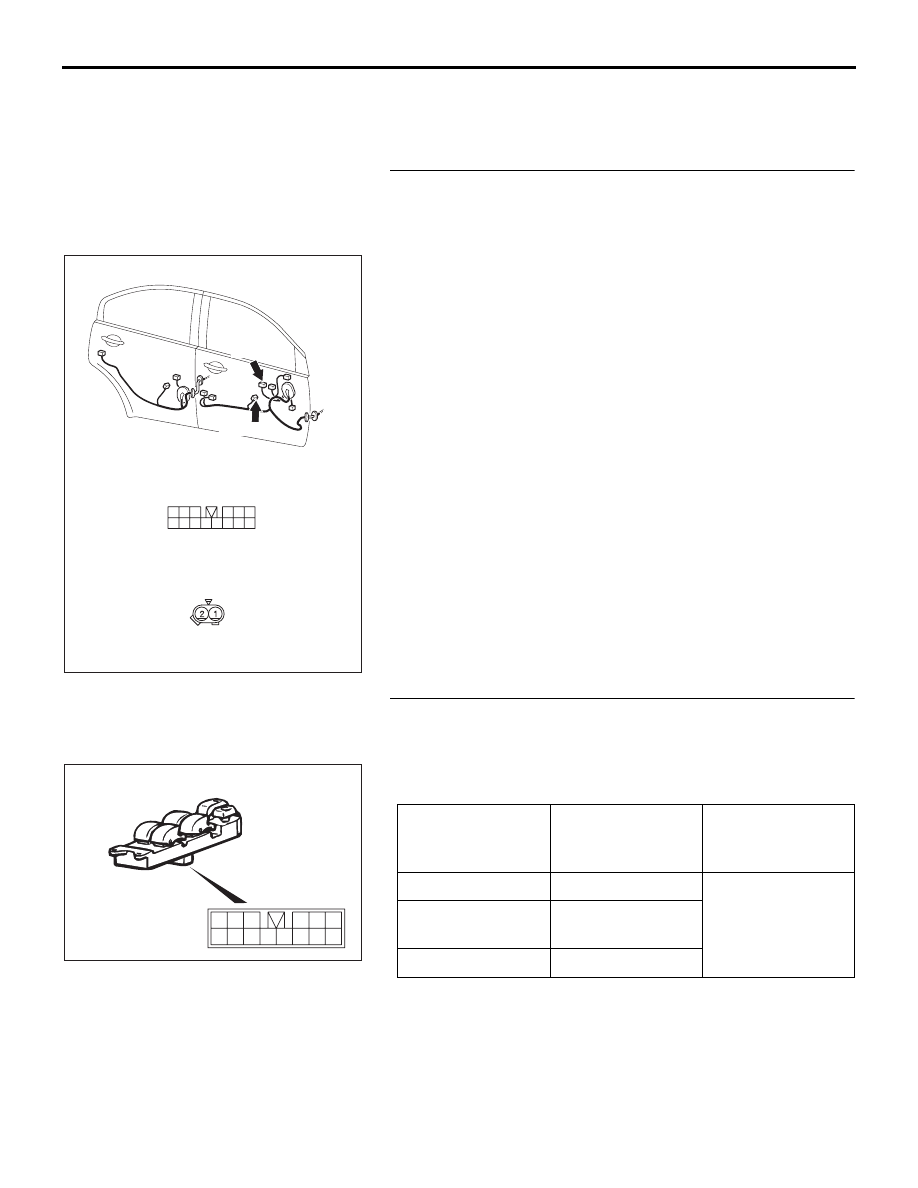
STEP 1. Check power window main switch connector E-04
and front power window regulator motor (RH) connector
E-03 for loose, corroded or damaged terminals, or
terminals pushed back in the connector.
Q: Are power window main switch connector E-04 and
front power window regulator motor (RH) connector
E-03 in good condition?
YES : Go to Step 2.
NO : Repair or replace the damaged component(s). Refer
to GROUP 00E, Harness Connector Inspection
. When the power window main switch is
operated, the front power window (RH) should lower
or raise normally.
STEP 2. Check the power window main switch.
(1) Remove the power window main switch. Refer to GROUP
42, Door, Door Glass and Regulator
.
(2) Check continuity while power window main switch is moved
to "UP" and "DOWN" position.
Q: Is the power window main switch normal?
YES : Go to Step 3.
NO : Replace the power window main switch. When the
power window main switch is operated, the front
power window (RH) should lower or raise normally.
16DB337A
CONNECTORS:E-04,E-03
3
9
4
12
14
6
13
5
1110
8
2
7
1
HARNESS SIDE
E-04
E-03
E-04
E-03(GR)
HARNESS SIDE
FRONT (RH)
SWITCH
POSITION
TESTER
CONNECTION
SPECIFIED
CONDITION
UP
12
− 10, 14 − 2
Less than 2 ohms
OFF
12
− 14, 12 − 2,
14
− 2
DOWN
12
− 2, 14 − 10
16DB338A
12
7
1
8
2
10
9
3
11
13
5
4
14
6