Mitsubishi 380. Manual - part 35


  Index      Mitsubishi     Mitsubishi 380 - service repair manual 2005 year


Search            


Content   ..  33  34  35  36   ..


Mitsubishi 380. Manual - part 35


SYMPTOM PROCEDURES

SIMPLIFIED WIRING SYSTEM (SWS)

54B-137

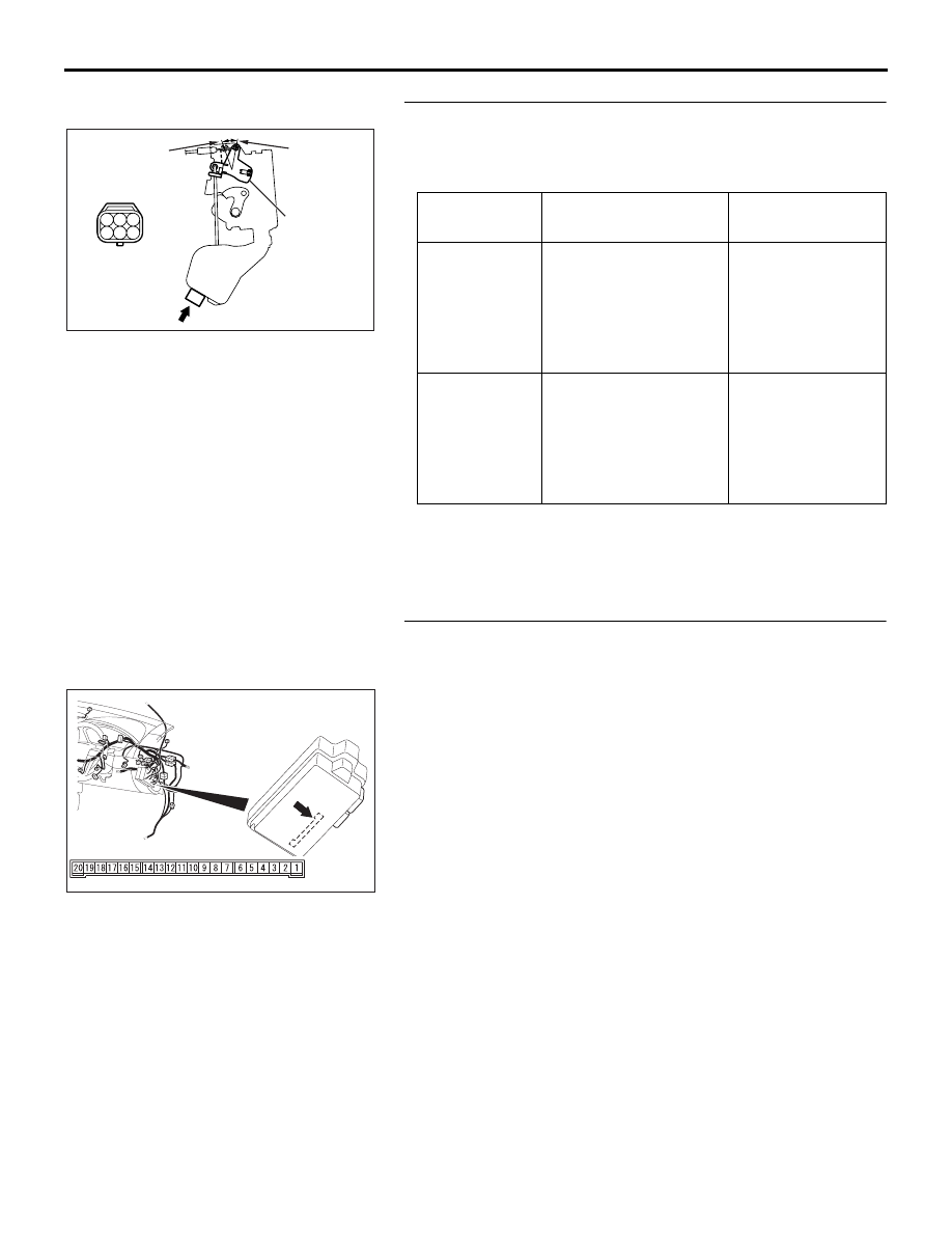
STEP 12. Check the rear door lock actuator (LH).
Remove the rear door lock actuator (LH). The illustration shows 
when the door lock actuator is viewed from outside the door. 
Refer to GROUP 42 

− Door Handle and Latch 

P.42-46

.

Q: Does the rear door lock actuator (LH) work normally?

YES : Go to Step 13.
NO :  Replace the rear door lock actuator (LH). Verify that 

all the doors can be locked and unlocked normally.

STEP 13. Check ETACS-ECU connector C-219 for loose, 
corroded or damaged terminals, or terminals pushed back 
in the connector.
Q: Is ETACS-ECU connector C-219 in good condition?

YES : Go to Step 14.
NO :  Repair or replace the damaged component(s). Refer 

to GROUP 00E, Harness Connector Inspection 

P.00E-2

. Verify that all the doors can be locked and 

unlocked normally.

LEVER 
POSITION

BATTERY 
CONNECTION

LEVER 
OPERATION

At the "LOCK" 
position

• Connect terminal 6 

to the negative 
battery terminal

• Connect terminal 4 

to the positive 
battery terminal

The lever moves 
from the "LOCK" 
position to the 
"UNLOCK" 
position.

At the 
"UNLOCK" 
position

• Connect terminal 4 

to the negative 
battery terminal

• Connect terminal 6 

to the positive 
battery terminal

The lever moves 
from the 
"UNLOCK" position 
to the "LOCK" 
position.

1 2 3

4 5 6

AC210906

A

VIEW A

LOCK

UNLOCK

LEVER

AB

54DB014A

CONNECTOR: C-219

JUNCTION BLOCK SIDE

JUNCTION BLOCK

(REAR VIEW)

SYMPTOM PROCEDURES

SIMPLIFIED WIRING SYSTEM (SWS)

54B-138

STEP 14. Check the wiring harness between ETACS-ECU 
connector C-219 (terminals 12 and 13) and rear door lock 
actuator (LH) connector E-18 (terminals 4 and 6).

NOTE: Also check intermediate connector D-19 and junction 
block connector C-204 for loose, corroded, or damaged termi-
nals, or terminals pushed back in the connector. If intermediate 
connector D-19 or junction block connector C-204 is damaged, 
repair or replace the damaged component(s) as described in 
GROUP 00E, Harness Connector Inspection 

P.00E-2

.

Q: Is the wiring harness between ETACS-ECU connector 

C-219 (terminals 12 and 13) and rear door lock actuator 
(LH) connector E-18 (terminals 4 and 6) in good 
condition?
YES : 
Replace the ETACS-ECU. Verify that all the doors 

can be locked and unlocked normally.

NO :  The wiring harness may be damaged or the 

connector(s) may have loose, corroded or damaged 
terminals, or terminals pushed back in the connector. 
Repair the wiring harness as necessary. Verify that all 
the doors can be locked and unlocked.

54DB014A

CONNECTOR: C-219

JUNCTION BLOCK SIDE

JUNCTION BLOCK

(REAR VIEW)

16DB323A

E-18 (B)

HARNESS SIDE

CONNECTOR: E-18

16DB325A

CONNECTOR: D-19

SYMPTOM PROCEDURES

SIMPLIFIED WIRING SYSTEM (SWS)

54B-139

STEP 15. Check rear door lock actuator (RH) connector 
E-08 for loose, corroded or damaged terminals, or 
terminals pushed back in the connector.
Q: Is rear door lock actuator (RH) connector E-08 in good 

condition?
YES : 
Go to Step 16.
NO :  Repair or replace the damaged component(s). Refer 

to GROUP 00E, Harness Connector Inspection 

P.00E-2

. Verify that all the doors can be locked and 

unlocked normally.

STEP 16. Check the rear door lock actuator (RH).
Remove the rear door lock actuator (RH). The illustration 
shows when the door lock actuator is viewed from outside the 
door. Refer to GROUP 42 

− Door Handle and Latch 

P.42-46

.

Q: Does the rear door lock actuator (RH) work normally?

YES : Go to Step 17.
NO :  Replace the rear door lock actuator (RH). Verify that 

all the doors can be locked and unlocked normally.

AC305333

E-08 (B)

HARNESS SIDE

CONNECTOR: E-08

AI

LEVER 
POSITION

BATTERY 
CONNECTION

LEVER 
OPERATION

At the "LOCK" 
position

• Connect terminal 

4 to the negative 
battery terminal

• Connect terminal 

6 to the positive 
battery terminal

The lever moves 
from the "LOCK" 
position to the 
"UNLOCK" 
position.

At the 
"UNLOCK" 
position

• Connect terminal 

6 to the negative 
battery terminal

• Connect terminal 

4 to the positive 
battery terminal

The lever moves 
from the 
"UNLOCK" position 
to the "LOCK" 
position.

AC210730

1 2 3

4 5 6

A

AB

VIEW A

LOCK

UNLOCK

LEVER

SYMPTOM PROCEDURES

SIMPLIFIED WIRING SYSTEM (SWS)

54B-140

STEP 17. Check ETACS-ECU connector C-219 for loose, 
corroded or damaged terminals, or terminals pushed back 
in the connector.
Q: Is ETACS-ECU connector C-219 in good condition?

YES : Go to Step 18.
NO :  Repair or replace the damaged component(s). Refer 

to GROUP 00E, Harness Connector Inspection 

P.00E-2

. Verify that all the doors can be locked and 

unlocked normally.

STEP 18. Check the wiring harness between ETACS-ECU 
connector C-219 (terminals 12 and 13) and rear door lock 
actuator (RH) connector E-08 (terminals 6 and 4).

54DB014A

CONNECTOR: C-219

JUNCTION BLOCK SIDE

JUNCTION BLOCK

(REAR VIEW)

54DB014A

CONNECTOR: C-219

JUNCTION BLOCK SIDE

JUNCTION BLOCK

(REAR VIEW)

AC305333

E-08 (B)

HARNESS SIDE

CONNECTOR: E-08

AI


Content   ..  33  34  35  36   ..