Mitsubishi 380. Manual - part 26


  Index      Mitsubishi     Mitsubishi 380 - service repair manual 2005 year


Search            


Content   ..  24  25  26  27   ..


Mitsubishi 380. Manual - part 26


SYMPTOM PROCEDURES

SIMPLIFIED WIRING SYSTEM (SWS)

54B-101

Normal condition is not displayed for "FRONT DOOR 
SW" : 
Refer to Inspection Procedure M-4 "ETACS-ECU 

does not receive any signal from the front door 
switches 

P.54B-413

."

Normal condition is not displayed for "H/L AUTO-CUT" : 

Refer to Inspection Procedure H-9 "Headlamp 
automatic shutoff function does not work normally 

P.54B-305

."

Normal condition is not displayed for "BUZZER" : 

Replace the ETACS-ECU. The lamp reminder tone 
alarm function should now work normally.

INSPECTION PROCEDURE B-3: Tone Alarm: Seat Belt Tone Alarm Function does not Work Normally.

NOTE: This troubleshooting procedure requires the 
use of diagnostic tool MB991958 and SWS monitor 
kit MB991813. For details on how to use the SWS 
monitor, refer to "How to connect SWS monitor 

P.54B-13

."

.

CIRCUIT OPERATION

The ETACS-ECU receives the driver's seat belt 
switch ON signal from the ignition switch (IG1) and 
the combination meter, and then controls the seat 
belt tone alarm function.
The ETACS-ECU operates the seat belt tone alarm 
function under the following conditions:

• Ignition switch: "ON" position

• Driver's seat belt: Unfastened

.

TECHNICAL DESCRIPTION (COMMENT)

If the seat belt tone alarm does not work, connec-
tor(s), wiring harness in the CAN bus lines, the com-
bination meter, the ETACS-ECU or the input signal 
circuit may be defective.

.

TROUBLESHOOTING HINTS

• Refer to circuit diagrams GROUP-

90

• Refer to configuration diagrams GROUP-

80

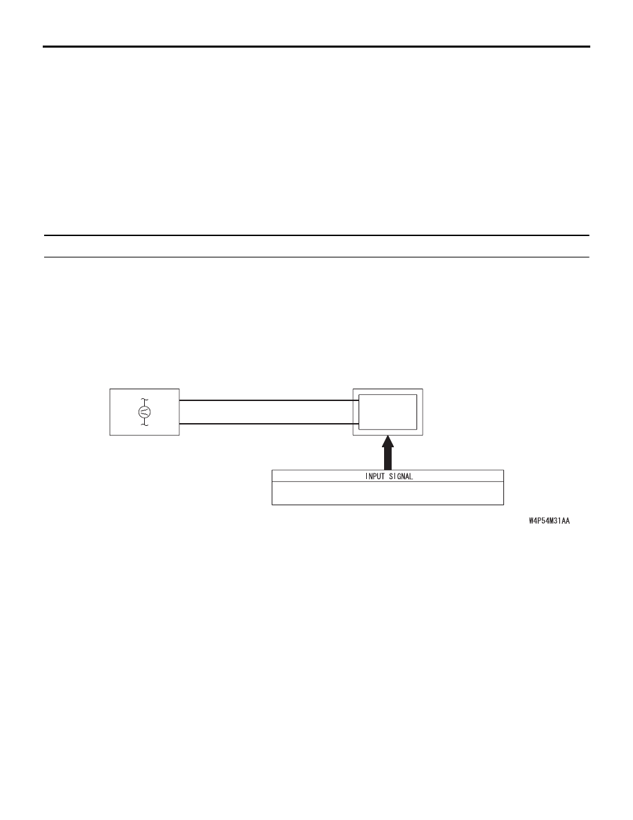
• Trouble in input signal system

• The wiring harness or connectors may have 

loose, corroded, or damaged terminals, or termi-
nals pushed back in the connector

• The ETACS-ECU may be defective

ETACS-

ECU

· 

SEAT BELT BUCKLE

 SWITCH (DRIVER'S SIDE)

· IGNITION SWITCH (IG1)

COMBINATION

METER

CPU

CAN COMMUNICATION LINE

(CAN_L LINE)

CAN COMMUNICATION LINE

(CAN_H LINE)

Seat Belt Tone Alarm Function

SYMPTOM PROCEDURES

SIMPLIFIED WIRING SYSTEM (SWS)

54B-102

DIAGNOSIS

Required Special Tools:

• MB991223: Harness Set

• MB991958: diagnostic tool (MUT-III Sub Assembly)

• MB991824: Vehicle Communication Interface (V.C.I.)

• MB991827: MUT-III USB Cable

• MB991910: MUT-III Main Harness A

• MB991813: SWS Monitor Kit

• MB991806: SWS Monitor Cartridge

• MB991812: SWS Monitor Harness (For Column-ECU)

• MB991822: Test Probe Harness

STEP 1. Using diagnostic tool MB991958, diagnose the 
CAN bus line.

CAUTION

To prevent damage to diagnostic tool MB991958, always 
turn the ignition switch to the "LOCK" (OFF) position 
before connecting or disconnecting diagnostic tool 
MB991958.
(1) Connect diagnostic tool MB991958. Refer to "How to 

connect SWS monitor 

P.54B-13

."

(2) Turn the ignition switch to the "ON" position.
(3) Diagnose the CAN bus line.
(4) Turn the ignition switch to the "LOCK" (OFF) position.

Q: Is the CAN bus line found to be normal?

YES : Go to Step 2.
NO :  Repair the CAN bus line (Refer to GROUP 54C, 

Diagnosis 

P.54C-5

).

00DB076A

MB991910

DATA LINK

CONNECTOR

MB991824

MB991827

SYMPTOM PROCEDURES

SIMPLIFIED WIRING SYSTEM (SWS)

54B-103

STEP 2. Using diagnostic tool MB991958, read the 
combination meter diagnostic trouble code. 
Check whether the combination meter-related DTC is set.
(1) Turn the ignition switch to the "ON" position.
(2) Check whether the combination meter-related DTC is set.
(3) Turn the ignition switch to the "LOCK" (OFF) position.

Q: Is the DTC set?

YES : Diagnose the multi center display unit (Refer to 

GROUP 54A, Diagnosis 

P.54A-254

).

NO :  Go to Step 3.

00DB076A

MB991910

DATA LINK

CONNECTOR

MB991824

MB991827

SYMPTOM PROCEDURES

SIMPLIFIED WIRING SYSTEM (SWS)

54B-104

STEP 3. Use diagnostic tool MB991958 to select "ECU 
COMM Check" on the SWS monitor display. 
Check the ETACS-ECU.

CAUTION

Connect special tool MB991910 before connecting special 
tool MB991812. Be sure to connect special tool MB991806 
after turning on special tool MB991824.
(1) Connect the SWS monitor. Refer to "How to connect SWS 

monitor 

P.54B-13

."

(2) Turn the ignition switch to the "LOCK" (OFF) position.
(3) Operate diagnostic tool MB991958 according to the 

procedure below to display "ECU COMM Check."
a. Select "Interactive Diagnosis."
b. Select "System Select."
c. Select "SWS."
d. Select "SWS MONITOR."
e. Select "ECU COMM Check."

(4) diagnostic tool MB991958 should show "OK" on the "ECU 

COMM Check" menu for the "ETACS ECU" menu.

Q: Is "OK" displayed for the "ETACS ECU" menu?

YES : Go to Step 4.
NO :  Refer to Inspection Procedure A-3 "Communication 

with the ETACS-ECU is not possible 

P.54B-74

."

00DB076A

MB991910

DATA LINK

CONNECTOR

MB991824

MB991827

AC302210

COLUMN SWITCH 
CONNECTOR

COLUMN SWITCH 
CONNECTOR AT 
HARNESS SIDE 

MB991812

AB


Content   ..  24  25  26  27   ..