Mitsubishi 380. Manual - part 17


  Index      Mitsubishi     Mitsubishi 380 - service repair manual 2005 year


Search            


Content   ..  15  16  17  18   ..


Mitsubishi 380. Manual - part 17


SYMPTOM PROCEDURES

SIMPLIFIED WIRING SYSTEM (SWS)

54B-65

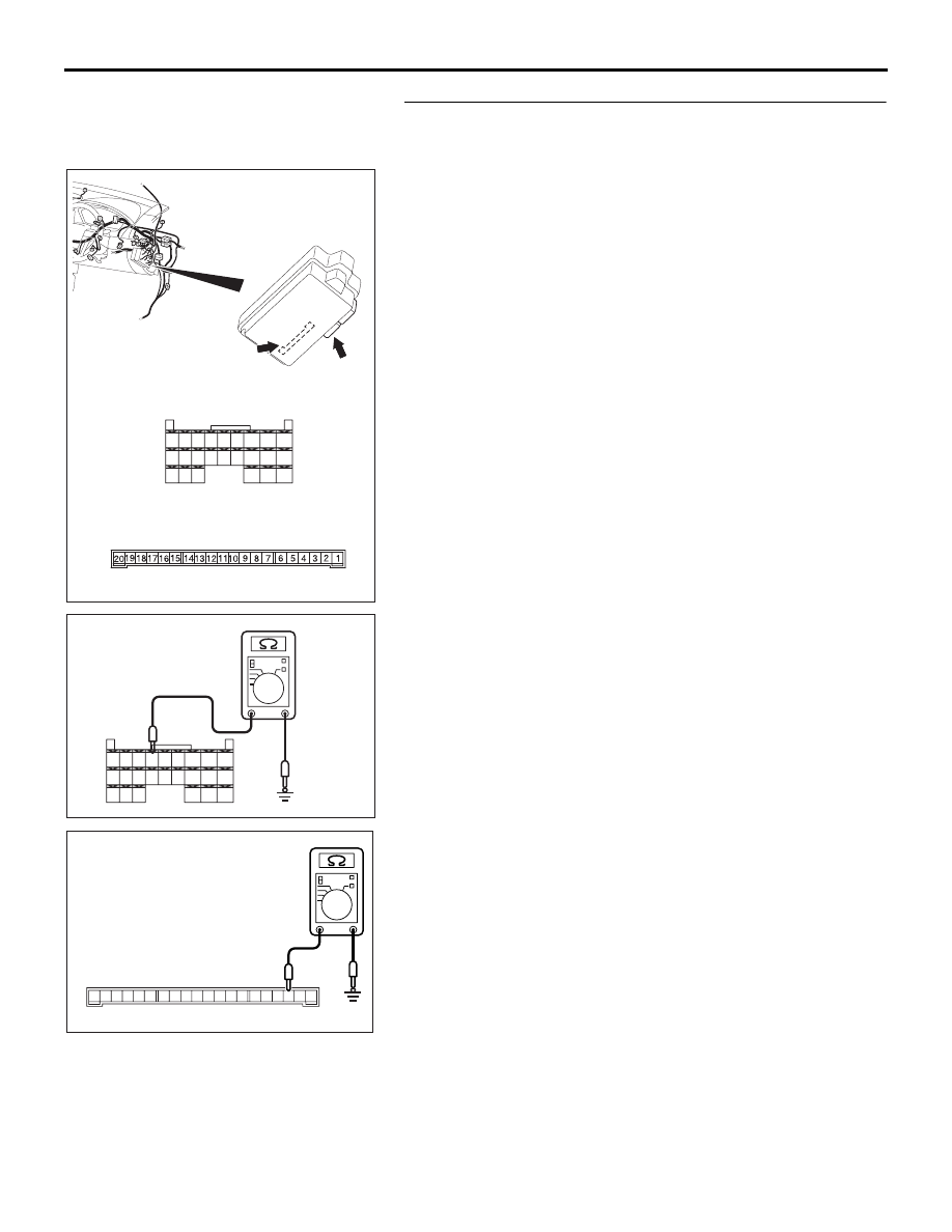
STEP 4. Check the ground circuit to the ETACS-ECU. 
Measure the resistance at ETACS-ECU connectors C-218 
and C-219.
(1) Disconnect ETACS-ECU connectors C-218 and C-219, and 

measure the resistance available at the junction block side 
of the connector.

(2) Measure the resistance value between ETACS-ECU 

connector C-218 terminal 50 and ground.

• The resistance should be 2 ohms or less.

Measure the resistance value between ETACS-ECU 
connector C-219 terminal 3 and ground.

• The resistance should be 2 ohms or less.

Q: Is the measured resistance 2 ohms or less?

YES : Go to Step 6.
NO :  Go to Step 5.

54DB045A

CONNECTORS: C-218, C-219

JUNCTION BLOCK
(REAR VIEW)

C-219

C-218 (GR)

HARNESS SIDE

C-218

C-219

JUNCTION BLOCK SIDE

45

46

48 47

49

50
59

51
60

52

53
62

65

61

54
63

56

68

64

67 66

57

58

55

54DB046A

CONNECTOR C-218
(HARNESS SIDE)

45

46

48 47

49

50
59

51
60

52

53
62

65

61

54
63

56

68

64

67 66

57

58

55

201918 171615 1413 1211 10 9 8 7 6 5 4 3 2 1

AC209857AB

CONNECTOR C-219
(JUNCTION BLOCK SIDE)

SYMPTOM PROCEDURES

SIMPLIFIED WIRING SYSTEM (SWS)

54B-66

STEP 5. Check the wiring harness between ETACS-ECU 
connector C-218 (terminal 50) or ETACS-ECU connector 
C-219 (terminal 3) and ground.

NOTE: Also check junction block connector C-211 for loose, 
corroded, or damaged terminals, or terminals pushed back in 
the connector. If junction block connector C-211 is damaged, 
repair or replace the damaged component(s) as described in 
GROUP 00E, Harness Connector Inspection 

P.00E-2

.

Q: Is the wiring harness between ETACS-ECU connector 

C-218 (terminal 50) or ETACS-ECU connector C-219 
(terminal 3) and ground in good condition?
YES : 
No action is necessary and testing is complete.
NO :  The wiring harness may be damaged or the 

connector(s) may have loose, corroded or damaged 
terminals, or terminals pushed back in the connector. 
Repair the wiring harness as necessary. Verify that 
the system should communicate with the SWS 
monitor kit normally.

54DB045A

CONNECTORS: C-218, C-219

JUNCTION BLOCK
(REAR VIEW)

C-219

C-218 (GR)

HARNESS SIDE

C-218

C-219

JUNCTION BLOCK SIDE

45

46

48 47

49

50
59

51
60

52

53
62

65

61

54
63

56

68

64

67 66

57

58

55

52DB023A

CONNECTOR: C-211

C-211

HARNESS SIDE

JUNCTION BLOCK

(FRONT VIEW)

SYMPTOM PROCEDURES

SIMPLIFIED WIRING SYSTEM (SWS)

54B-67

STEP 6. Check data link connector C-125 for loose, 
corroded or damaged terminals, or terminals pushed back 
in the connector.
Q: Is data link connector C-125 in good condition?

YES : Go to Step 7.
NO :  Repair or replace the damaged component(s). Refer 

to GROUP 00E, Harness Connector Inspection 

P.00E-2

. Verify that the system should communicate 

with the SWS monitor kit normally.

STEP 7. Check the wiring harness between ETACS-ECU 
connector C-218 (terminals 45, 53 and 61) and data link 
connector C-125 (terminals 9, 3 and 1).
Q: Is the wiring harness between ETACS-ECU connector 

C-218 (terminals 45, 53 and 61) and data link connector 
C-125 (terminals 9, 3 and 1) in good condition?
YES : 
Replace the ETACS-ECU. The system should 

communicate with the SWS monitor kit normally.

NO :  The wiring harness may be damaged or the 

connector(s) may have loose, corroded or damaged 
terminals, or terminals pushed back in the connector. 
Repair the wiring harness as necessary. Verify that 
the system should communicate with the SWS 
monitor kit normally.

54DB047A

CONNECTOR:C-125

C-125 (B)

FRONT SIDE

54DB006A

CONNECTORS: C-218

JUNCTION BLOCK
(REAR VIEW)

C-218 (GR)

HARNESS SIDE

45

46

48 47

49

50
59

51
60

52

53
62

65

61

54
63

56

68

64

67 66

57

58

55

SYMPTOM PROCEDURES

SIMPLIFIED WIRING SYSTEM (SWS)

54B-68

INSPECTION PROCEDURE A-2: Communication with the Column Switch (column-ECU) is not 
Possible.

NOTE: This troubleshooting procedure requires the 
use of diagnostic tool MB991958 and SWS monitor 
kit MB991813. For details on how to use the SWS 
monitor, refer to "How to connect SWS monitor 

P.54B-13

."

.

CIRCUIT OPERATION

• The power supply to the column switch is pro-

vided by the battery and the ignition switch (IG1).

• If the power supply system from the battery is 

defective, the system operates by the power sup-
ply from the ignition switch (IG1).

• Refer to circuit diagrams GROUP-

90

• Refer to configuration diagrams GROUP-

80

.

TECHNICAL DESCRIPTION (COMMENT)

The power supply circuit to the column switch (col-
umn-ECU) may be defective. If the battery power 
supply circuit (terminal 1 of the column switch) to the 
ECU is damaged, also check the power supply circuit 
from the ignition switch (IG1) (terminal 9 of the col-
umn switch), and repair if necessary.

.

TROUBLESHOOTING HINTS

• The wiring harness or connectors may have 

loose, corroded, or damaged terminals, or termi-
nals pushed back in the connector

• The column switch may be defective

• The ETACS-ECU may be defective

DIAGNOSIS

Required Special Tools:

• MB991223: Harness Set

• MB991958: DIAGNOSTIC TOOL (MUT-III Sub Assembly)

• MB991824: Vehicle Communication Interface (V.C.I.)

• MB991827: MUT-III USB Cable

• MB991910: MUT-III Main Harness A

• MB991813: SWS Monitor Kit

• MB991806: SWS Monitor Cartridge

• MB991812: SWS Monitor Harness (For Column-ECU)

• MB991822: Probe Harness

54DB002A

CONNECTOR: C-218

C-218 (GR)

HARNESS SIDE

45

46

48 47

49

50
59

51
60

52

53
62

65

61

54
63

56

68

64

67 66

57

58

55

54DB050A

CONNECTOR: C-309


Content   ..  15  16  17  18   ..