Mitsubishi Grandis. Manual - part 947


  Index      Mitsubishi     Mitsubishi Grandis - service repair manual


Search            


Content   ..  945  946  947  948   ..


Mitsubishi Grandis. Manual - part 947


TROUBLESHOOTING

TRACTION CONTROL/ACTIVE STABILITY CONTROL SYSTEM

35C-113

CAUTION

If diagnosis code No.U1104 is set in the 
TCL/ASC-ECU, always diagnose the CAN bus 
lines.

CAUTION

Whenever the ECU is replaced, ensure that the 
CAN bus lines are normal.

OPERATION

The TCL/ASC-ECU and the steering wheel sensor 
are connected each other via a CAN bus line, and 
the sensor sends the steering wheel angle 
information to the ECU.

DIAGNOSIS CODE SET CONDITIONS

Current trouble

• Connector(s) or wiring harness in the CAN bus 

lines between the TCL/ASC-ECU and the 
steering wheel sensor, the power supply system 
to the steering wheel sensor, the steering wheel 
sensor itself, or the TCL/ASC-ECU may be 
defective.

Past trouble

• Carry out diagnosis with particular emphasis on 

connector(s) or wiring harness in the CAN bus 
lines between the steering wheel sensor and the 
TCL/ASC-ECU, and the power supply system to 
the steering wheel sensor. For diagnosis 
procedures, refer to "How to cope with past 
trouble" (Refer to GROUP 00, How to Use 
Troubleshooting/Inspection Service Points 

P.00-5

).

NOTE: For a past trouble, you may not find it by the 

MUT-III CAN bus diagnostics even if there is any 
failure in CAN bus lines. In this case, refer to 
GROUP 00, How to Use 
Troubleshooting/Inspection Service Points 

 How 

to Cope with Intermittent Malfunction 

P.00-5

). 

and check the CAN bus lines. You can narrow 
down the possible cause of the trouble by 
referring to the diagnosis code, which is set 
regarding the CAN communication-linked ECUs 
(Refer to GROUP 54D, CAN bus line Diagnostic 
flow 

P.54D-9

).

PROBABLE CAUSES

• The CAN bus line is defective.

• Malfunction of the hydraulic unit (integrated with 

TCL/ASC-ECU)

• Malfunction of the steering wheel sensor

DIAGNOSIS

STEP 1. MUT-III CAN bus diagnostics
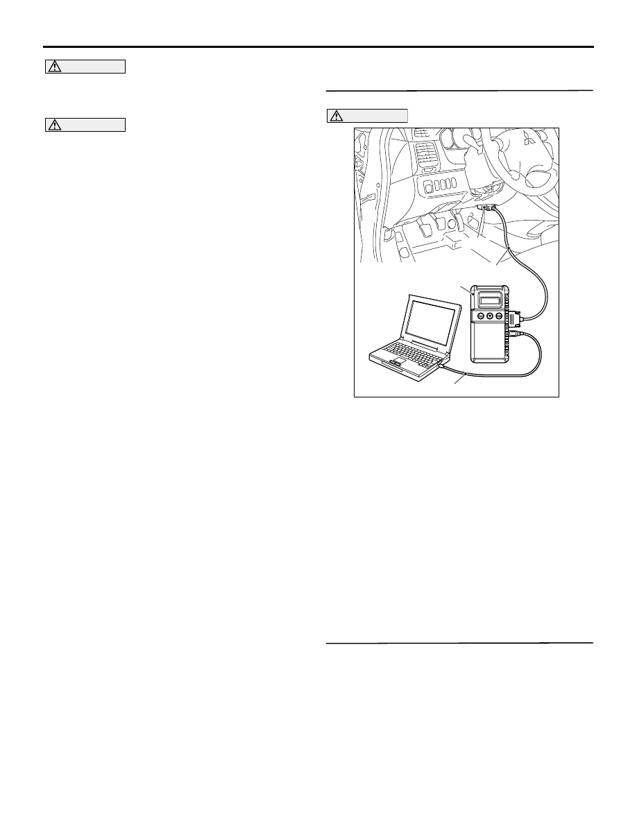
CAUTION

To prevent damage to MUT-III, always turn the 
ignition switch to the "LOCK" (OFF) position 
before connecting or disconnecting MUT-III.
(1) Connect the MUT-III to the diagnosis connector 

as shown in the illustration.

(2) Turn the ignition switch to the "ON" position.
(3) Diagnose the CAN bus line. (Refer to GROUP 

54D, CAN bus line Diagnostic flow 

P.54D-9

).

(4) Turn the ignition switch to the "LOCK" (OFF) 

position.

(5) Disconnect MUT-III.

Q: Is the check result normal?

YES : 

Go to Step 2

NO : 

Repair the CAN bus lines (Refer to GROUP 
54D, CAN bus line Diagnostic flow 

P.54D-9

). On completion, go to Step 6.

STEP 2. MUT-III steering wheel sensor diagnosis 
code
Check if a steering wheel sensor diagnosis code is 
set.

Q: Is the diagnosis code set?

YES : 

Diagnose the steering wheel sensor by 

referring to 

P.35C-6

.

NO : 

Go to Step 3.

AC302297

AC310120

AB

MB991827

16-pin

MB991910

MB991824

TROUBLESHOOTING

TRACTION CONTROL/ACTIVE STABILITY CONTROL SYSTEM

35C-114

STEP 3. MUT-III other system diagnosis code

Check if a diagnosis code, which relates to CAN 
communication-linked systems below, is set.

Engine-A/T-ECU <A/T> or Engine-ECU <M/T>

• Code No.U1100: TCL/ASC-ECU time-out

Combination meter

• Code No.011: TCL/ASC-ECU time-out

Q: Is the diagnosis code set?

YES : 

Go to Step 4.

NO : 

Go to Step 5.

STEP 4. Check whether the diagnosis code is 
reset.

Recheck if the diagnosis code is set.
(1) Erase the diagnosis code.
(2) Turn the ignition switch to "ON" position.
(3) Check if the diagnosis code is set.

Q: Is any diagnosis code set?

YES : 

A poor connection, open circuit or other 

intermittent malfunction is present in the 
CAN bus lines between the steering wheel 
sensor and the TCL/ASC-ECU (Refer to 
GROUP 00, How to Use 
Troubleshooting/Inspection Service Points 

− 

How to Cope with Intermittent Malfunction 

P.00-5

).

NO : 

Replace hydraulic unit (integrated with 
TCL/ASC-ECU) and then go to Step 6.

STEP 5. Check whether the diagnosis code is 
reset.

Recheck if the diagnosis code is set.
(1) Erase the diagnosis code.
(2) Turn the ignition switch to "ON" position.
(3) Check if the diagnosis code is set.

Q: Is any diagnosis code set?

YES : 

A poor connection, open circuit or other 

intermittent malfunction is present in the 
CAN bus lines between the steering wheel 
sensor and the TCL/ASC-ECU (Refer to 
GROUP 00, How to Use 
Troubleshooting/Inspection Service Points 

− 

How to Cope with Intermittent Malfunction 

P.00-5

).

NO : 

Replace steering wheel sensor and then go 
to Step 6.

STEP 6. Check whether the diagnosis code is 
reset.

Recheck if the diagnosis code is set.
(1) Erase the diagnosis code.
(2) Turn the ignition switch to "ON" position.
(3) Check if the diagnosis code is set.

Q: Is any diagnosis code set?

YES : 

The procedure is complete.

NO : 

Go to Step 1.

Code No.U1120 CAN communications system TCL uncontrollable by engine malfunction

CAUTION

• If diagnosis code No.U1120 is set in the 

TCL/ASC-ECU, always diagnose the CAN 
main bus line. If there is any fault in the CAN 
bus lines, an incorrect diagnosis code may be 
set.

• Whenever the ECU is replaced, ensure that 

the communication circuit is normal.

DIAGNOSIS CODE SET CONDITION

The TCL/ASC-ECU receives engine system-related 
signals from the Engine-ECU <M/T> or 
Engine-A/T-ECU <A/T> via CAN bus lines. If a 
fail-safe related data is contained in the signal from 
the Engine-ECU <M/T> or Engine-A/T-ECU <A/T>, 
diagnosis code No.U1120 will be stored.

PROBABLE CAUSES

• Damaged harness or connector.

• Malfunction of the Engine-ECU <M/T> or 

Engine-A/T-ECU <A/T>.

• Malfunction of the TCL/ASC-ECU.

TROUBLESHOOTING

TRACTION CONTROL/ACTIVE STABILITY CONTROL SYSTEM

35C-115

DIAGNOSIS

STEP 1. MUT-III other system diagnosis code

CAUTION

To prevent damage to MUT-III, always turn the 
ignition switch to the "LOCK" (OFF) position 
before connecting or disconnecting MUT-III.
(1) Connect the MUT-III to the diagnosis connector 

as shown in the illustration.

(2) Turn the ignition switch to the "ON" position.
(3) Check for MPI system diagnosis code (Refer to 

GROUP 13A, MPI Diagnosis - Diagnosis 
Function 

P.13A-11

).

(4) Turn the ignition switch to the "LOCK" (OFF) 

position.

(5) Disconnect MUT-III.

Q: Is any diagnosis code set?

YES : 

Repair the MPI control system. (Refer to 

GROUP 13A, MPI Diagnosis - Diagnosis 
Function 

P.13A-11

). Then go to Step 6 .

NO : 

Go to Step 2 .

STEP 2. MUT-III CAN bus diagnostics

CAUTION

To prevent damage to MUT-III, always turn the 
ignition switch to the "LOCK" (OFF) position 
before connecting or disconnecting MUT-III.
(1) Connect the MUT-III to the diagnosis connector 

as shown in the illustration.

(2) Turn the ignition switch to the "ON" position.
(3) Diagnose the CAN bus line. (Refer to GROUP 

54D, CAN bus line Diagnostic flow 

P.54D-9

).

(4) Turn the ignition switch to the "LOCK" (OFF) 

position.

(5) Disconnect MUT-III.

Q: Is the check result normal?

YES : 

Go to Step 3 .

NO : 

Repair the CAN bus line (Refer to GROUP 
54D, CAN bus line Diagnostic flow 

P.54D-9

). Then go to Step 6.

AC302297

AC310120

AB

MB991827

16-pin

MB991910

MB991824

AC302297

AC310120

AB

MB991827

16-pin

MB991910

MB991824

TROUBLESHOOTING

TRACTION CONTROL/ACTIVE STABILITY CONTROL SYSTEM

35C-116

STEP 3. MUT-III other system diagnosis code

CAUTION

To prevent damage to MUT-III, always turn the 
ignition switch to the "LOCK" (OFF) position 
before connecting or disconnecting MUT-III.
(1) Connect the MUT-III to the diagnosis connector 

as shown in the illustration.

(2) Turn the ignition switch to the "ON" position.
(3) Check if a diagnosis code, which relates to CAN 

communication-linked systems below, is set.
A/C-ECU

• Code No.U1120: Engine-related CAN 

communication failure information

(4) Turn the ignition switch to the "LOCK" (OFF) 

position.

(5) Disconnect MUT-III.

Q: Is code No.U1120 set?

YES : 

Go to Step 4 .

NO : 

Go to Step 5 .

STEP 4. Check whether the diagnosis code is 
reset.

Check again if the diagnosis code is set.

CAUTION

To prevent damage to MUT-III, always turn the 
ignition switch to the "LOCK" (OFF) position 
before connecting or disconnecting MUT-III.
(1) Connect the MUT-III to the diagnosis connector 

as shown in the illustration.

(2) Turn the ignition switch to the "ON" position.

(3) Erase the diagnosis code (Refer to 

P.35C-6

).

(4) Turn the ignition switch to the "LOCK" (OFF) 

position.

(5) Turn the ignition switch to the "ON" position.
(6) Check if the diagnosis code is set.
(7) Turn the ignition switch to the "LOCK" (OFF) 

position.

(8) Disconnect MUT-III.

Q: Is code No.U1120 set?

YES : 

Replace the Engine-ECU <M/T> or 

Engine-A/T-ECU <A/T> (Refer to GROUP 
13A, Engine-ECU and Engine-A/T-ECU 

P.13A-399

). Then go to Step 6 .

NO : 

It can be assumed that this malfunction is 
intermittent. Refer to GROUP 00, How to 
Use Troubleshooting/Inspection Service 
Points 

− How to Cope with Intermittent 

Malfunction 

P.00-5

.

AC302297

AC310120

AB

MB991827

16-pin

MB991910

MB991824

AC302297

AC310120

AB

MB991827

16-pin

MB991910

MB991824


Content   ..  945  946  947  948   ..