Mitsubishi Grandis. Manual - part 915
ON-VEHICLE SERVICE
ANTI-SKID BRAKING SYSTEM (ABS)
35B-75
RESISTANCE AND CONTINUITY
BETWEEN HARNESS-SIDE CONNECTOR
TERMINALS
1. Turn the ignition switch to the "LOCK" (OFF)
position and disconnect the ABS-ECU connectors
before checking resistance and continuity.
2. Check the resistance and continuity between the
terminals indicated in the table below.
3. The terminal layout is shown in the illustration.
ON-VEHICLE SERVICE
HYDRAULIC UNIT CHECK
M1352001700675
CAUTION
• The roller of the braking force tester and the
tyre should be dry during testing.
• When testing the front brakes, apply the
parking brake. When testing the rear brakes,
stop the front wheels with chocks.
1. Jack up the vehicle. Then support the vehicle with
rigid racks at the specified jack-up points or place
the front or rear wheels on the rollers of the
braking force tester.
2. Release the parking brake, and feel the drag force
(drag torque) on each road wheel. When using
the braking force tester, take a reading of the
brake drag force.
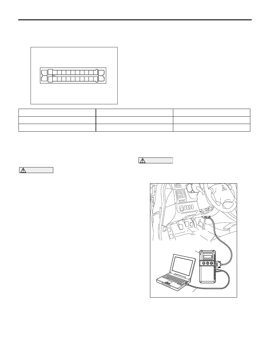
CAUTION
To prevent damage to MUT-III, always turn the
ignition switch to the "LOOK" (OFF) position
before connecting or disconnecting the MUT-III.
3. Turn the ignition switch to the "LOCK" (OFF)
position and set the MUT-III as shown in the
illustration.
4. After checking that the shift lever is in neutral,
start the engine.
AC313001
1
3
4
5
6
7
8
9
10
11
2
13 12
16
17
18
19
20
21
22
23
24
15
25
14
26
ABS-ECU terminal No.
Signal
Normal condition
13
− body earth
Earth
Less than 2
Ω
26
− body earth
Earth
Less than 2
Ω
AC302297
AC310120
AB
MB991827
16-pin
MB991910
MB991824