Mitsubishi Grandis. Manual - part 906


  Index      Mitsubishi     Mitsubishi Grandis - service repair manual


Search            


Content   ..  904  905  906  907   ..


Mitsubishi Grandis. Manual - part 906


TROUBLESHOOTING

ANTI-SKID BRAKING SYSTEM (ABS)

35B-39

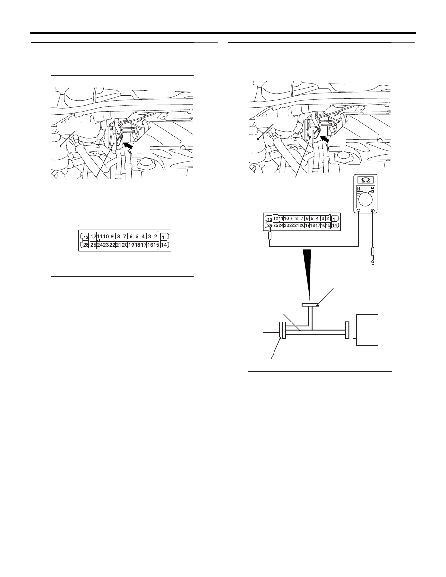
STEP 4. Check ABS-ECU connector A-03 for 
loose, corroded or damaged terminals, or 
terminals pushed back in the connector.

Q: Is the check result normal?

YES : 

An open or short circuit may be present in 

the solenoid valve power supply circuit. 
Repair the wiring harness between 
ABS-ECU connector A-03 terminal 1 and 
fusible link No.3. Then go to Step 8.

NO : 

Repair or replace the damaged 
component(s). Then go to Step 8.

STEP 5. Resistance measurement at ABS-ECU 
connector A-03.

(1) Disconnect the connector A-03, and connect 

special tool ABS Check Harness (MB991974) to 
the wiring harness-side connector.
NOTE: Do not connect special tool ABS Check 
Harness (MB991974) to the ABS-ECU.

(2) Measure the resistance between terminal 26 and 

earth.

OK: 2 ohm or less

Q: Is the check result normal?

YES : 

Go to Step 7.

NO : 

Go to Step 6.

AC312621

Oil reservoir

Connector: A-03

AC

A-03

Hydraulic unit
(with built-in ABS-ECU)

A-03 Harness connector
(harness side)

AC312620AH

Oil reservoir

Connector: A-03

ABS-ECU

MB991974

Check connector

A-03 Harness connector

A-03

Hydraulic unit
(with built-in ABS-ECU)

TROUBLESHOOTING

ANTI-SKID BRAKING SYSTEM (ABS)

35B-40

STEP 6. Check ABS-ECU connector A-03 for 
loose, corroded or damaged terminals, or 
terminals pushed back in the connector.

Q: Is the check result normal?

YES : 

An open circuit may be present in the earth 

circuit. Repair the wiring harness between 
ABS-ECU connector A-03 terminal 1 and 
the body earth. Then go to Step 8 .

NO : 

Repair or replace the damaged 
component(s). Then go to Step 8.

STEP 7. Check whether the diagnosis code is 
reset.

Check again if the diagnosis code is set.
(1) Turn the ignition switch to the "ON" position.
(2) Erase the diagnosis code.
(3) Turn the ignition switch to the "LOCK" (OFF) 

position.

(4) Turn the ignition switch to the "ON" position.
(5) Check if the diagnosis code is set.
(6) Turn the ignition switch to the "LOCK" (OFF) 

position.

Q: Is code No.C1226, C1231, C1236, C1241, C1246, 

C1251, C1256 or C1261 set?

YES : 

Replace the hydraulic unit (integrated with 

ABS-ECU). Then go to Step 8.

NO : 

It can be assumed that this malfunction is 
intermittent. Refer to GROUP 00, How to 
Use Troubleshooting/Inspection Service 
Points 

− How to Cope with Intermittent 

Malfunction 

P.00-5

.

AC312621

Oil reservoir

Connector: A-03

AC

A-03

Hydraulic unit
(with built-in ABS-ECU)

A-03 Harness connector
(harness side)

AC302297

AC310120

AB

MB991827

16-pin

MB991910

MB991824

TROUBLESHOOTING

ANTI-SKID BRAKING SYSTEM (ABS)

35B-41

STEP 8. Check whether the diagnosis code is 
reset.

Check again if the diagnosis code is set.
(1) Turn the ignition switch to the "ON" position.

(2) Erase the diagnosis code.
(3) Turn the ignition switch to the "LOCK" (OFF) 

position.

(4) Turn the ignition switch to the "ON" position.
(5) Check if the diagnosis code is set.
(6) Turn the ignition switch to the "LOCK" (OFF) 

position.

Q: Is code No.C1226, C1231, C1236, C1241, C1246, 

C1251, C1256 or C1261 set?

YES : 

Go to Step 1.

NO : 

The procedure is complete.

AC302297

AC310120

AB

MB991827

16-pin

MB991910

MB991824

TROUBLESHOOTING

ANTI-SKID BRAKING SYSTEM (ABS)

35B-42

Code No. C1271: Motor drive circuit (Abnormal power supply voltage)

CAUTION

If there is any problem in the CAN bus lines, an 
incorrect diagnosis code may be set. Diagnose 
the CAN bus lines before the Diagnosis codes 
(Refer to GROUP 54D, CAN bus-line diagnostic 
flow 

P.54D-9

).

OPERATION

• The ABS-ECU contains the power supply circuit 

(terminal 14) for the pump motor. The pump 
motor is energized by the motor switch, which is 
incorporated in the ABS-ECU.

• The pump motor switch, which is incorporated in 

the ABS-ECU, is always off unless the motor 
solenoid valve check is activated when the 
vehicle is started.

• The ABS-ECU activates the pump motor by 

turning on the ECU built-in pump motor switch 
when the ABS is working.

DIAGNOSIS CODE SET CONDITIONS

The most likely causes for these diagnosis codes to 
set are:

• This code is set if the pump motor power supply 

voltage is abnormally low for long time when the 
pump motor does not operate.

• This code is set if the pump motor voltage is 

abnormally high for long time when the pump 
motor does not operate.

• This code is set if the pump motor switch voltage 

drop indicates high value when the pump motor 
operates.

3

FUSIBLE 
LINK

4

FUSIBLE 
LINK

ABS-ECU

SOLENOID 
VALVE POWER 
SOURCE

SOLENOID 
VALVE POWER 
SOURCE

SOLENOID VALVE

HYDRAULIC UNIT

MOTOR 
POWER
SOURCE

MOTOR 
POWER
SOURCE

Wire colour code
B : Black     LG : Light green     G : Green     L : Blue
W : White     Y : Yellow     SB : Sky blue     BR : Brown
O : Orange     GR : Gray     R : Red     P : Pink     V : Violet

Solenoid Valve and Motor Power Supply Circuit


Content   ..  904  905  906  907   ..