Mitsubishi Grandis. Manual - part 885
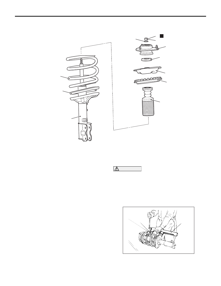
STRUT ASSEMBLY
FRONT SUSPENSION
33-7
DISASSEMBLY AND REASSEMBLY
M1332001300448
DISASSEMBLY SERVICE POINTS
<<A>> STRUT NUT (SELF-LOCKING NUT)
REMOVAL
CAUTION
• Install special tool arm set (MB991238) evenly,
and so that the maximum length will be
attained within the installation range.
• Do not use an impact wrench to tighten the
bolt of special tool spring compressor body
(MB991237), otherwise the special tool will
break.
1. Use following special tools to compress the coil
spring.
• Arm set (MB991795)
• Spring compressor (MB991237)
AC301981AC
75 ± 5 N·m
8
7
10
9
1
2
3
4
5
N
6
Disassembly steps
<<A>> >>C<<
1.
Strut nut (self-locking nut)
2.
Strut washer
3.
Strut insulator assembly
>>B<<
4.
Strut bearing
5.
Spring upper seat
6.
Spring upper pad
>>A<<
7.
Coil spring
8.
Spring lower pad
9.
Strut damper
<<B>>
10. Strut assembly
AC001085 AB
MB991238
MB991237