Mitsubishi Grandis. Manual - part 866


  Index      Mitsubishi     Mitsubishi Grandis - service repair manual


Search            


Content   ..  864  865  866  867   ..


Mitsubishi Grandis. Manual - part 866


ON-VEHICLE SERVICE

AUTOMATIC TRANSMISSION (FF)

23A-131

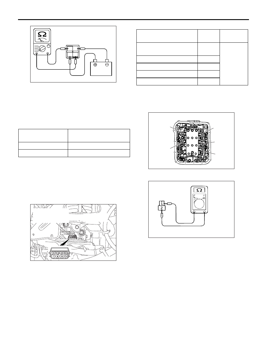
2. Use the jumper leads to connect A/T control relay 

terminal 2 to the negative battery terminal and 
terminal 3 to the positive battery terminal.

3. Check the continuity between A/T control relay 

connector terminals 1 and 4 while alternately 
connecting and disconnecting the jumper leads 
from the battery terminals.

4. If there is a malfunction, replace the A/T control 

relay.

A/T CONTROL SOLENOID VALVE 
ASSEMBLY CHECK

M1231009400320

1. Use the MUT-III to measure the ATF temperature 

and check that the ATF temperature is 20

°C.

2. Disconnect the A/T control solenoid valve 

assembly connector.

3. Measure the resistance between the solenoid 

valve terminals.

4. Check that the measured values are within the 

standard values at items 1 and 3.

Standard value:

5. If within the standard value, check the power 

supply and the earth circuits.

6. If not within the standard value, drain the ATF and 

remove the valve body cover.

7. Disconnect the solenoid valve connectors.

8. Measure the resistance between terminals 1 and 

2 at each solenoid valve side.

Standard value: 2.7 

 3.4  (A/T fluid 

temperature 20

°C)

9. If not within the standard value, replace the 

solenoid valve.

10.If within the standard value, check the harness 

wire between A/T control solenoid valve assembly 
connector and each solenoid valve connector. If a 
problem is not found at the steps above, check 
the solenoid valve O-rings and replace if 
necessary.

A/T FLUID TEMPERATURE SENSOR 
CHECK

M1231004500300

1. Drain the ATF and remove the valve body cover.

Jumper leads

Continuity between 
terminals 1 and 4

Connected

Less than 2 

Disconnected

Open circuit

AC100115

1 2
3 4

AQ

AC303628AE

Transmission
mount

A/T control
solenoid valve
assembly connector

Name

Terminal 
No.

Resistance 
value

Damper clutch control 
solenoid valve

− 10

2.7 

− 3.4 Ω 

(A/T fluid 
temperatur
e 20

°C)

Low-reverse solenoid valve 6 

− 10

Second solenoid valve

− 9

Underdrive solenoid valve

− 9

Overdrive solenoid valve

− 9

AC002219

OD

solenoid

valve

LR

solenoid

valve

UD

solenoid

valve

2ND

solenoid

valve

DCC

solenoid

valve

CO

AC002289

ON-VEHICLE SERVICE

AUTOMATIC TRANSMISSION (FF)

23A-132

2. Remove the A/T fluid temperature sensor.

3. Measure the resistance between A/T control 

solenoid valve assembly connector terminals 1 
and 2.

Standard value:

NOTE: The A/T fluid temperature warning lamp 
on the combination meter flashes when the 
temperature reaches approximately 125 

°

C or 

higher and then stops flashing when the 
temperature drops below approximately 115

°

C.

4. If the A/T fluid temperature sensor resistance and 

the temperature when the N range indicator is 
flashing or switched off are outside the standard 
value ranges, replace the A/T fluid temperature 
sensor.

TORQUE CONVERTER STALL TEST

M1231005400425

The purpose of this test is to measure the maximum 
engine speed when the torque converter stalls in D 
or R ranges in order to check the torque converter 
(Stator and one-way clutch operation) and the 
holding performance of the clutches and brakes 
which are built into the transmission.

WARNING

For safety, the front and rear of the vehicle 
should be kept clear of other people while 
this test is being carried out.

1. Check the A/T fluid level, the A/T fluid 

temperature and the engine coolant temperature.

• A/T fluid level: HOT position on oil level gauge

• A/T fluid temperature: 70 − 80°C

• Engine coolant temperature: 80 − 100°C

NOTE: The A/T fluid temperature is measured 
with MUT-III.

2. Place wheel locks on both the left and right front 

wheels.

3. Pull the parking brake lever to apply the parking 

brake and depress the brake pedal fully.

4. Start the engine.

Fluid temperature 
(

°C)

Resistance value (

)

0

16.7 

− 20.5

20

7.3 

− 8.9

40

3.4 

− 4.2

60

1.9 

− 2.2

80

1.0 

− 1.2

100

0.57 

− 0.69

AC002219CF

A/T fluid 
temperature 
sensor

AC103441

ATF

AB

AC001824AC

Reverse
clutch

Low-reverse
brake

Underdrive
clutch

Torque
converter

Second brake

Overdrive 
clutch

One-way 
clutch

ON-VEHICLE SERVICE

AUTOMATIC TRANSMISSION (FF)

23A-133

CAUTION

• Do not keep the throttle fully open for any 

longer than 5 seconds.

• If you repeat the stall test when the A/T fluid 

temperature is greater than 80

°C, move the 

selector lever to the "N" position and let the 
engine run at approximately 1,000 r/min for at 
least one minute. Wait until the A/T fluid 
temperature returns to 80

°C or less.

5. Move the selector lever to the D position, fully 

depress the accelerator pedal and quickly take a 
reading of the maximum engine speed at this 
time.

Standard stalling engine speed: 2, 300 

 2, 

800 r/min

6. Move the selector lever to the R position and 

repeat the test described above.

Standard stalling engine speed: 2, 300 

 2, 

800 r/min

TORQUE CONVERTER STALL TEST 
JUDGMENT RESULTS

1. Stall speed is too high in both D and R ranges

• Malfunction of the torque converter (Slippage 

on the splines of the torque converter and the 
input shaft)

• Low line pressure

• Low-reverse brake slippage and malfunction 

of the one-way clutch

2. Stall speed is too high in D range only

• Underdrive clutch slippage

3. Stall speed is too high in R range only

• Reverse clutch slippage

4. Stall speed is too low in both D and R ranges

• Malfunction of the torque converter (Slippage 

of the one-way clutch)

• Low line pressure

• Poor engine output

HYDRAULIC PRESSURE TESTS

M1231005500455

CAUTION

The transmission fluid temperature should be 
between 70 

 80°C during the test.

1. Check the transmission fluid level, temperature 

and engine coolant temperature.

• Transmission fluid level: HOT mark on the 

dipstick

• Transmission fluid temperature: 70 − 80°C

• Engine coolant temperature: 80 − 100°C

2. Raise the vehicle so that the wheels are free to 

turn.

3. Connect the special tools (oil pressure gauge (3.0 

MPa) [MD998330] and adapters [MD998332, 
MD998900]) to each pressure discharge port.
NOTE: 

.

2ND: Second brake pressure port

UD: Underdrive clutch pressure port

LR: Low-reverse brake pressure port

DR: Torque converter release pressure port

DA: Torque converter apply pressure port

RV: Reverse clutch pressure port

OD: Overdrive clutch pressure port

4. Restart the engine.
5. Check that there are no leaks around the special 

tool port adapters.

6. Measure the hydraulic pressure at each port 

under the conditions given in the standard 
hydraulic pressure table, and check that the 
measured values are within the standard value 
ranges.

AC006150

<Under side view>

Valve body cover

MD998332

MD998330

AC

AC006149

MD998332

MD998330

Valve body cover

AC

AC006151AC

MD998900

MD998330

Valve body
cover

ON-VEHICLE SERVICE

AUTOMATIC TRANSMISSION (FF)

23A-134

7. If the pressure is not within the standard value, 

stop the engine and refer to the hydraulic 
pressure test diagnosis table.

8. Remove the O-ring from the port plug and replace 

it.

9. Remove the special tool, and install the plugs to 

the hydraulic pressure ports.

10.Start the engine and check that there are no leaks 

around the plugs.


Content   ..  864  865  866  867   ..