Mitsubishi Grandis. Manual - part 851
TROUBLESHOOTING <A/T>
AUTOMATIC TRANSMISSION (FF)
23A-71
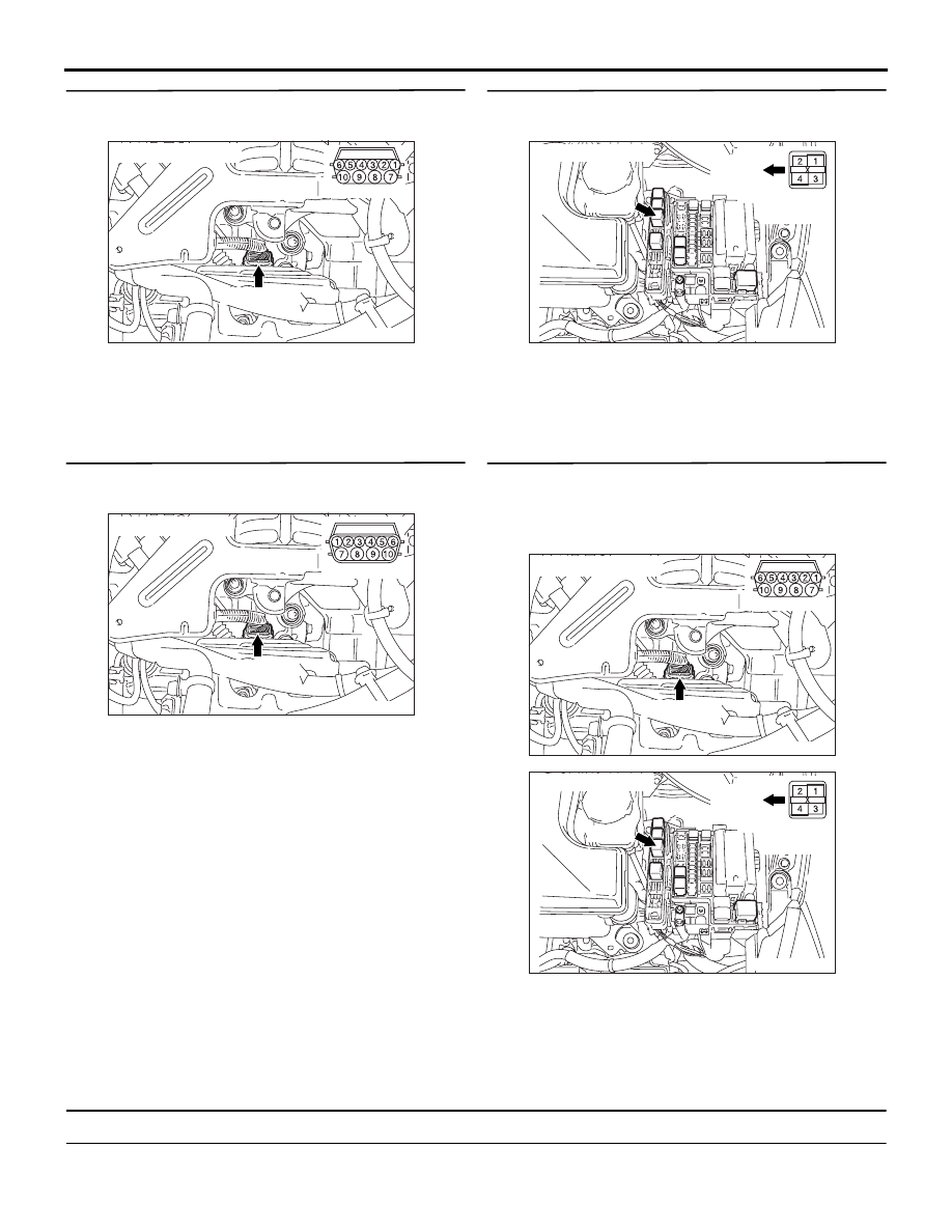
STEP 9. Connector check: B-109 A/T control
solenoid valve assembly connector
Check for the contact with terminals.
Q: Is the check result normal?
YES :
Go to Step 10.
NO :
Repair the defective connector.
STEP 10. Measure the resistance at A/T control
solenoid valve assembly connector B-109.
Disconnect the connector, and measure the
resistance between terminal No.4 and No.9 at the
solenoid valve side.
OK: 2.7
− 3.4 Ω (A/T fluid temperature 20°C))
Q: Is the check result normal?
YES :
Go to Step 11.
NO :
Check the solenoid valve harness.
STEP 11. Connector check: B-14X A/T control
relay connector
Check for the contact with terminals.
Q: Is the check result normal?
YES :
Go to Step 12.
NO :
Repair the defective connector.
STEP 12. Check the harness between A/T control
solenoid valve assembly connector B-109
terminal No.9 and A/T control relay connector
B-14X terminal No.1.
Check the power supply line for short or open circuit.
Q: Is the check result normal?
YES :
Go to Step 8.
NO :
Repair the wiring harness.
Code No.34: Overdrive solenoid valve system
SOLENOID VALVE SYSTEM CIRCUIT
Refer to
.
AC303628
B-109 (GR)
Harness side
AG
Connector: B-109
AC303628AF
B-109 (GR)
Connector: B-109
Sensor side
AC311979AC
B-14X
Connector: B-14X
Front of
vehicle
Relay box
side
AC303628
B-109 (GR)
Harness side
AG
Connector: B-109
AC311979AC
B-14X
Connector: B-14X
Front of
vehicle
Relay box
side