Mitsubishi Grandis. Manual - part 787


  Index      Mitsubishi     Mitsubishi Grandis - service repair manual


Search            


Content   ..  785  786  787  788   ..


Mitsubishi Grandis. Manual - part 787


ENGINE-ECU AND ENGINE-A/T-ECU

MULTIPORT FUEL INJECTION (MPI)

13A-399

ENGINE-ECU AND ENGINE-A/T-ECU

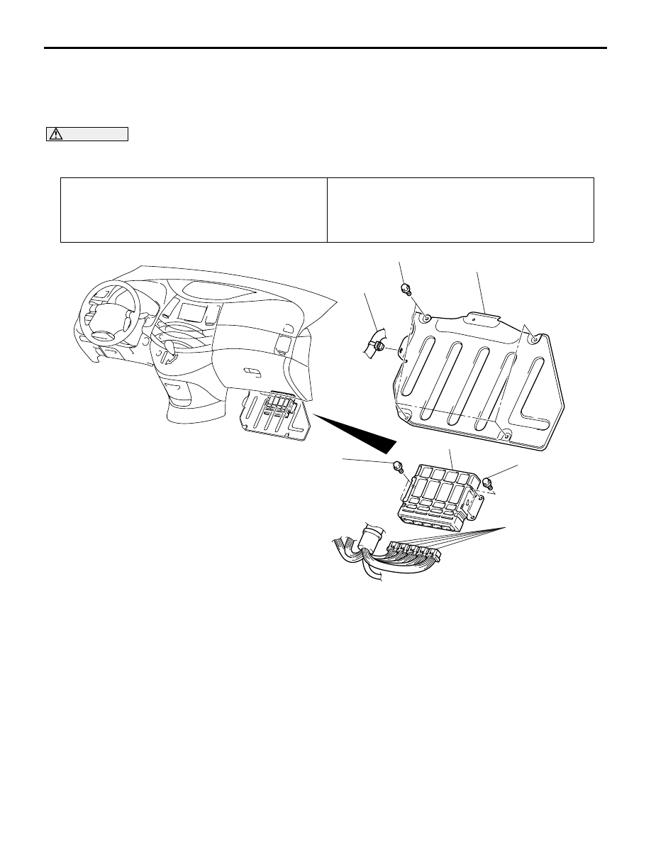
REMOVAL AND INSTALLATION

M1131022500053

<L.H. drive vehicles>

CAUTION

Always register the ignition key(s) when the engine-ECU <M/T> or the engine-A/T-ECU <A/T> is 
replaced (Refer to GROUP 54A, On-vehicle Service - Immobilizer ID Code Registration 

P.54A-26

).

INSTALLATION SERVICE POINT
>>A<< LNITIALIZATION

When the Engine-ECU <M/T> or Engine-A/T-ECU 
<A/T> is replaced, initialize the electronic-controlled 
throttle valve system according to the procedure 
below beforehand.

Turn the ignition switch to the ON position, and 
back to the "LOCK" (OFF) position. Then hold it in 
this position for approximately 10 seconds or 
more.

Pre-removal Operation
• Front Scuff Plate (RH), Cowl Side Trim (RH) Removal 

(Refer to GROUP 52A Trims 

P.52A-10

).

• Console Side Cover (RH) Removal (Refer to GROUP 

52A, Floor Console assembly 

P.52A-9

).

Post-installation Operation
• Console Side Cover (RH) Installation (Refer to GROUP 

52A, Floor Console assembly 

P.52A-9

).

• Front Scuff Plate (RH), Cowl Side Trim (RH) Installation 

(Refer to GROUP 52A Trims 

P.52A-10

).

AC310595

1

5.0 ± 1.0 N·m

2

3

4

5.0 ± 1.0 N·m

5.0 ± 1.0 N·m

AB

REMOVAL STEPS

>>A<<

Initialization (Installation only)

Turn up the floor mat. <Front 
passenger's side>

1.

Wiring harness clamp connection

2.

Bracket

3.

Engine-ECU connector <M/T> or 
Engine-A/T-ECU connector <A/T>

4.

Engine-ECU <M/T> or 
Engine-A/T-ECU <A/T>

ENGINE-ECU AND ENGINE-A/T-ECU

MULTIPORT FUEL INJECTION (MPI)

13A-400

<R.H. drive vehicles>

CAUTION

Always register the ignition key(s) when the engine-ECU <M/T> or the engine-A/T-ECU <A/T> is 
replaced (Refer to GROUP 54A, On-vehicle Service - Immobilizer ID Code Registration 

P.54A-26

).

INSTALLATION SERVICE POINT
>>A<< LNITIALIZATION

When the Engine-ECU <M/T> or Engine-A/T-ECU 
<A/T> is replaced, initialize the electronic-controlled 
throttle valve system according to the procedure 
below beforehand.

Turn the ignition switch to the ON position, and 
back to the "LOCK" (OFF) position. Then hold it in 
this position for approximately 10 seconds or 
more.

Pre-removal Operation
• Front Scuff Plate (LH), Cowl Side Trim (LH) Removal 

(Refer to GROUP 52A Trims 

P.52A-10

).

• Console Side Cover (LH) Removal (Refer to GROUP 

52A, Floor Console assembly 

P.52A-9

).

Post-installation Operation
• Console Side Cover (LH) Installation (Refer to GROUP 

52A, Floor Console assembly 

P.52A-9

).

• Front Scuff Plate (LH), Cowl Side Trim (LH) Installation 

(Refer to GROUP 52A Trims 

P.52A-10

).

AC301810

1

5.0 ± 1.0 N·m

2

3

4

5

5.0 ± 1.0 N·m

5.0 ± 1.0 N·m

AC301810AC

REMOVAL STEPS

>>A<<

Initialization (Installation only)

Turn up the floor mat. <Front 
passenger's side>

1.

Wiring harness clamp connection

2.

Wiring harness clamp connection

3.

Bracket

4.

Engine-ECU connector <M/T> or 
Engine-A/T-ECU connector <A/T>

5.

Engine-ECU <M/T> or 
Engine-A/T-ECU <A/T>

GENERAL INFORMATION

INTAKE AND EXHAUST

15-2

GENERAL INFORMATION

M1151000100509

The exhaust pipe is divided into three parts.

SERVICE SPECIFICATION

M1151000300525

SEALANT

M1151000500228

SPECIAL TOOL

M1151000600474

Item

Standard value

Limit

Manifold distortion of the installation surface   mm

0.15 or less

0.20

Item

Specified sealant

Thermostat case assembly

MITSUBISHI GENUINE Part No.MD970389 or equivalent

Thermostat case assembly bolt

3M Stud Locking 4170 or equivalent

Tool

Number

Name

Use

MB991953

Oxygen sensor wrench

Removal and installation of 
oxygen sensor

B991953


Content   ..  785  786  787  788   ..