Mitsubishi Grandis. Manual - part 770


  Index      Mitsubishi     Mitsubishi Grandis - service repair manual


Search            


Content   ..  768  769  770  771   ..


Mitsubishi Grandis. Manual - part 770


TROUBLESHOOTING

MULTIPORT FUEL INJECTION (MPI)

13A-331

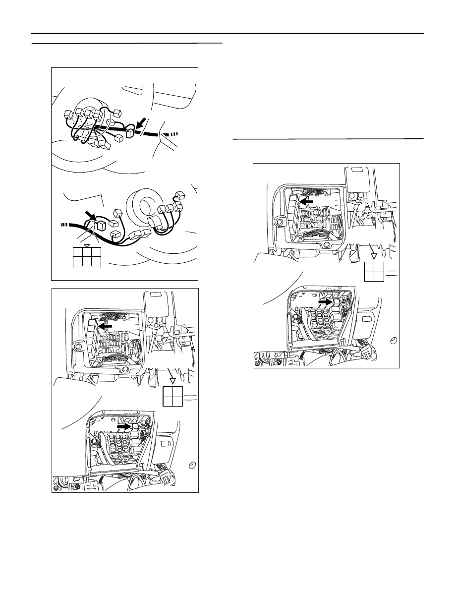
STEP 5. Connector check: C-307 ignition switch 
connector

Q: Is the check result normal? 

YES : 

Check intermediate connector C-202, and 

repair if necessary. If intermediate 
connector is normal, check and repair 
harness between C-216 (terminal No. 3) 
fuel pump relay (1) connector and C-307 
(terminal No. 2) ignition switch connector.

• Check power supply line for open 

circuit and damage.

NO : 

Repair or replace.

STEP 6. Perform voltage measurement at C-216 
fuel pump relay (1) connector.

• Remove relay, and measure at junction block 

side.

• Voltage between terminal No. 4 and earth.

OK: System voltage

Q: Is the check result normal?

YES : 

Go to Step 7 .

NO : 

Check intermediate connectors C-125 and 

C-203, and repair if necessary. If 
intermediate connectors are normal, check 
and repair harness between C-216 (terminal 
No. 4) fuel pump relay (1) connector and 
battery.

• Check power supply line for 

open/short circuit.

1

2

3

4

5

6

AK305629

 C-307

 C-307

Connector: C-307

Harness side connector

<R.H.drive vehicle>

<L.H.drive vehicle>

AB

AK305635

2 1

3

4

AB

Connector: C-216

C-216

Harness side
connector

C-216

Relay box’s
triangle marks

<L.H. drive vehicles>

<R.H. drive vehicles>

AK305635

2 1

3

4

AB

Connector: C-216

C-216

Harness side
connector

C-216

Relay box’s
triangle marks

<L.H. drive vehicles>

<R.H. drive vehicles>

TROUBLESHOOTING

MULTIPORT FUEL INJECTION (MPI)

13A-332

STEP 7. Perform voltage measurement at C-214 
fuel pump relay (2) connector.

• Remove relay, and measure at junction block 

side.

• Ignition switch: ON

• Voltage between terminal No. 3 and earth.

OK: System voltage

Q: Is the check result normal? 

YES : 

Go to Step 9 .

NO : 

Go to Step 8 .

STEP 8. Connector check: C-307 ignition switch 
connector

Q: Is the check result normal?

AK305634

2 1

3

4

AB

Connector: C-214

C-214

Harness side
connector

C-214

Relay box’s
triangle marks

<L.H. drive vehicles>

<R.H. drive vehicles>

1

2

3

4

5

6

AK305629

 C-307

 C-307

Connector: C-307

Harness side connector

<R.H.drive vehicle>

<L.H.drive vehicle>

AB

AK305634

2 1

3

4

AB

Connector: C-214

C-214

Harness side
connector

C-214

Relay box’s
triangle marks

<L.H. drive vehicles>

<R.H. drive vehicles>

TROUBLESHOOTING

MULTIPORT FUEL INJECTION (MPI)

13A-333

YES : 

Check intermediate connector C-202, and 

repair if necessary. If intermediate 
connector is normal, check and repair 
harness between C-307 (terminal No. 2) 
ignition switch connector and C-214 
(terminal No. 3) fuel pump relay (2) 
connector.

• Check power supply line for open 

circuit.

NO : 

Repair or replace.

STEP 9. Connector check: C-110 engine-ECU 
<M/T> connector or engine-A/T-ECU <A/T> 
connector

Q: Is the check result normal?

YES : 

Go to Step 10 .

NO : 

Repair or replace.

STEP 10. Perform voltage measurement at C-110 
engine-ECU <M/T> connector or engine-A/T-ECU 
<A/T> connector.

• Disconnect connector, and measure at harness 

side.

• Ignition switch: ON

• Voltage between terminal No. 16 and earth.

OK: System voltage

Q: Is the check result normal?

AK305618AB

1

2

3

4

5

6

7

8

9

10

11

12

13

14

15

16

17

18

19

20

21

22

23

24

25

26

27

Connector: C-110

<L.H. drive vehicles>

<R.H. drive vehicles>

C-110 (GR)

C-110 (GR)

Harness side connector

AK305618AB

1

2

3

4

5

6

7

8

9

10

11

12

13

14

15

16

17

18

19

20

21

22

23

24

25

26

27

Connector: C-110

<L.H. drive vehicles>

<R.H. drive vehicles>

C-110 (GR)

C-110 (GR)

Harness side connector

AK305634

2 1

3

4

AB

Connector: C-214

C-214

Harness side
connector

C-214

Relay box’s
triangle marks

<L.H. drive vehicles>

<R.H. drive vehicles>

TROUBLESHOOTING

MULTIPORT FUEL INJECTION (MPI)

13A-334

YES : 

Go to Step 11 .

NO : 

Check intermediate connectors C-18 and 

C-205, and repair if necessary. If 
intermediate connectors are normal, check 
and repair harness between C-214 (terminal 
No. 2) fuel pump relay (2) connector and 
C-110 (terminal No. 16) engine-ECU <M/T> 
connector or engine-A/T-ECU <A/T> 
connector.

• Check earthing line for open/short 

circuit.

STEP 11. Connector check: D-15 fuel pump 
connector

Q: Is the check result normal?

YES : 

Go to Step 12 .

NO : 

Repair or replace.

STEP 12. Perform voltage measurement at D-15 
fuel pump connector.

• Disconnect connector, and measure at harness 

side.

• Ignition switch: ON

• Using a jumper wire, connect C-110 (terminal No. 

16) engine-ECU <M/T> connector or 
engine-A/T-ECU <A/T> connector and earth.

• Voltage between terminal No. 5 and earth.

OK: System voltage

Q: Is the check result normal?

YES : 

Go to Step 15 .

NO : 

Go to Step 13 .

STEP 13. Check harness between C-216 (terminal 
No. 1) fuel pump relay (1) connector and C-214 
(terminal No. 1) fuel pump relay (2) connector.

• Check power supply line for open/short circuit.

Q: Is the check result normal?

YES : 

Go to Step 14 

NO : 

Repair.

AK301003

1

2

3

4

5

AC

Connector: D-15

 D-15 (GR)

Harness side
connector

AK301003

1

2

3

4

5

AC

Connector: D-15

 D-15 (GR)

Harness side
connector

AK305633

2 1

3

4

AB

Connectors: C-214, C-216

C-214

Harness side
connector

C-216

C-214

Relay box’s
triangle marks

C-216

<L.H. drive vehicles>

<R.H. drive vehicles>


Content   ..  768  769  770  771   ..