Mitsubishi Grandis. Manual - part 760


  Index      Mitsubishi     Mitsubishi Grandis - service repair manual


Search            


Content   ..  758  759  760  761   ..


Mitsubishi Grandis. Manual - part 760


TROUBLESHOOTING

MULTIPORT FUEL INJECTION (MPI)

13A-291

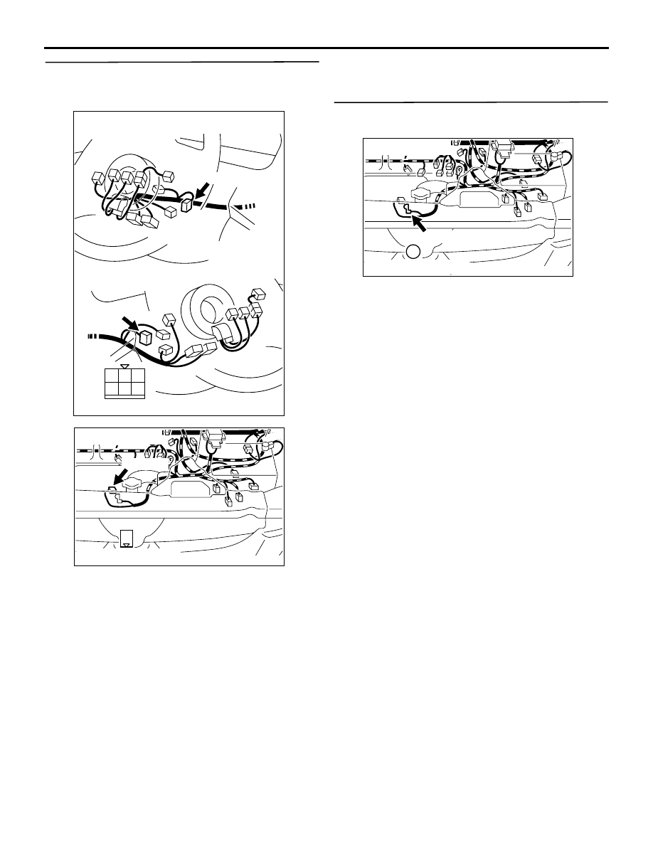
STEP 13: Check harness between C-307 (terminal 
No. 5) ignition switch connector and B-116 
(terminal No. 1) starter connector.

NOTE: Before checking harness, check intermediate 
connectors B-17 and C-18, and repair if necessary.

• Check output line for damage.

Q: Is the check result normal?

YES : 

Go to Step 14 .

NO : 

Repair.

STEP 14: Check harness between B-115 (terminal 
No. 1) starter connector and battery.

• Check power supply line for damage.

Q: Is the check result normal?

YES : 

Replace starter.

NO : 

Repair.

1

2

3

4

5

6

AK305629

 C-307

 C-307

Connector: C-307

Harness side connector

<R.H.drive vehicle>

<L.H.drive vehicle>

AB

AK305631

1

 B-116 (B)

Connector: B-116

Harness side connector

AB

AK305630

1

 B-115 

Connector: B-115

Harness side connector

AB

TROUBLESHOOTING

MULTIPORT FUEL INJECTION (MPI)

13A-292

Inspection Procedure 5: Starting Impossible (No Initial Combustion) <A/T>

COMMENT ON TROUBLE SYMPTOM

• Failure is possibly caused by failed starter itself 

or failed related circuit.

PROBABLE CAUSE

• Failed battery

• Failed inhibitor switch

• Failed starter motor

• Open/short circuit in starter associated circuit or 

loose connector contact

AK305576

1

5 6

1 2 3 4

7

8

9 10

1 2 3

4 5 6

31

35363738394041 42 43
444546474849

50 51

5253

545556

57 58

32

33 34

1

M

Battery

Inhibitor 
switch

OFF

ON

AB

Starter

B-115

B-116

(MU801211)

C-111

(MU803803)

B-111

(MU802355)

B-17

B-W

C-307

2

7

10

9

B-W

B-W

Engine-A/T-ECU

B-Y

B-L

1

51

1

B-Y

C-18

IG2

ST

LOCK

ACC

IG1

Ignition switch

5

Stating impossible (no initial combustion)  <A/T>

Wire colour code
B: Black  LG: Light green  G: Green  L: Blue  W: White  Y: Yellow  SB: Sky blue  BR: Brown  O: Orange  GR: Gray
R: Red  P: Pink  V: Violet

TROUBLESHOOTING

MULTIPORT FUEL INJECTION (MPI)

13A-293

DIAGNOSIS PROCEDURE

STEP 1: Check battery voltage.

• Measure battery voltage at cranking.

OK: 8 V or higher

Q: Is the check result normal?

YES : 

Go to Step 2.

NO : 

Check battery (Refer to GROUP 54A 

− 

Battery-On-vehicle Service 

− Battery Test 

P.54A-6

).

STEP 2: MUT-III data list

• Refer to Data List Reference Table 

P.13A-363

a. Item 18: Cranking signal

OK: 

ON (Ignition switch: ST)
OFF (Ignition switch: ON)

Q: Is the check result normal?

YES : 

Go to Step 11.

NO : 

Go to Step 3.

STEP 3: Connector check: C-111 engine-A/T-ECU 
connector

Q: Is the check result normal?

YES : 

Go to Step 4.

NO : 

Repair or replace.

STEP 4: Perform voltage measurement at C-111 
engine-A/T-ECU connector.

• Disconnect connector, and measure at the 

harness side.

• Ignition switch: ST

• Voltage between terminal No. 51 and earth.

OK: System voltage

Q: Is the check result normal?

YES : 

Go to Step 10.

NO : 

Go to Step 5.

STEP 5: Connector check: B-111 inhibitor switch 
connector

Q: Is the check result normal?

YES : 

Go to Step 6.

NO : 

Repair or replace.

AK305625AB

Connector: C-111

<L.H. drive vehicles>

<R.H. drive vehicles>

C-111 (GR)

C-111 (GR)

Harness side connector

31

32

33

34

35

36

37

38

39

40

41

42

43

44

45

46

47

48

49

52

53

54

55

56

57

58

50

51

AK305625AB

Connector: C-111

<L.H. drive vehicles>

<R.H. drive vehicles>

C-111 (GR)

C-111 (GR)

Harness side connector

31

32

33

34

35

36

37

38

39

40

41

42

43

44

45

46

47

48

49

52

53

54

55

56

57

58

50

51

AK305632

8

9

3

4

5

1

2

6

7

10

 B-111 (B)

Connector: B-111

Harness side connector

AB

TROUBLESHOOTING

MULTIPORT FUEL INJECTION (MPI)

13A-294

STEP 6: Perform voltage measurement at B-111 
inhibitor switch connector

• Disconnect connector, and measure at the 

harness side.

• Ignition switch: ST

• Voltage between terminal No. 10 and earth.

OK: System voltage

Q: Is the check result normal?

YES : 

Go to Step 9.

NO : 

Go to Step 7.

STEP 7: Connector check: C-307 ignition switch 
connector

Q: Is the check result normal?

YES : 

Go to Step 8.

NO : 

Repair or replace.

STEP 8: Check ignition switch

• Check ignition switch (Refer to GROUP 54A − 

Ignition switch 

− Inspection 

P.54A-31

).

Q: Is the check result normal?

YES : 

Check intermediate connector C-18 and 

repair if necessary. If intermediate 
connector is normal, check and repair 
harness between B-111 (terminal No. 10) 
inhibitor switch connector and C-307 
(terminal No. 5) ignition switch connector.

• Check power supply line for 

open/short circuit.

NO : 

Replace ignition switch.

AK305632

8

9

3

4

5

1

2

6

7

10

 B-111 (B)

Connector: B-111

Harness side connector

AB

1

2

3

4

5

6

AK305629

 C-307

 C-307

Connector: C-307

Harness side connector

<R.H.drive vehicle>

<L.H.drive vehicle>

AB

AK305632

8

9

3

4

5

1

2

6

7

10

 B-111 (B)

Connector: B-111

Harness side connector

AB

1

2

3

4

5

6

AK305629

 C-307

 C-307

Connector: C-307

Harness side connector

<R.H.drive vehicle>

<L.H.drive vehicle>

AB


Content   ..  758  759  760  761   ..