Mitsubishi Grandis. Manual - part 754


  Index      Mitsubishi     Mitsubishi Grandis - service repair manual


Search            


Content   ..  752  753  754  755   ..


Mitsubishi Grandis. Manual - part 754


TROUBLESHOOTING

MULTIPORT FUEL INJECTION (MPI)

13A-267

Code No. P2138: Accelerator Pedal Position Sensor (Main and Sub) Range/Performance Problem

OPERATION

• Refer to Code No. P2122: Accelerator Pedal 

Position Sensor (main) Circuit Low Input 

P.13A-248

.

• Refer to Code No. P2127: Accelerator Pedal 

Position Sensor (sub) Circuit Low Input 

P.13A-256

.

FUNCTION

• Engine-ECU <M/T> or engine-A/T-ECU <A/T> 

checks the accelerator pedal position sensor 
output signal characteristics for abnormal 
conditions.

TROUBLE JUDGMENT

Check Conditions

• Ignition switch is in ON position

• Accelerator pedal position sensor (main) output 

voltage is 0.2 

− 4.5 V.

• Accelerator pedal position sensor (sub) output 

voltage is 0.2 

− 4.5 V.

Judgment Criteria

• Accelerator pedal position sensor (sub) output 

voltage minus Accelerator pedal position sensor 
(main) output voltage is 1 volt or higher for 1 
second.

• Accelerator pedal position sensor (main) output 

voltage minus Accelerator pedal position sensor 
(sub) output voltage is 1 volt or higher for 0.2 
seconds.

PROBABLE CAUSE

• Failed accelerator pedal position sensor

• Open/short circuit in accelerator pedal position 

sensor circuit or loose connector contact

• Failed engine-ECU <M/T>

• Failed engine-A/T-ECU <A/T>

DIAGNOSIS PROCEDURE

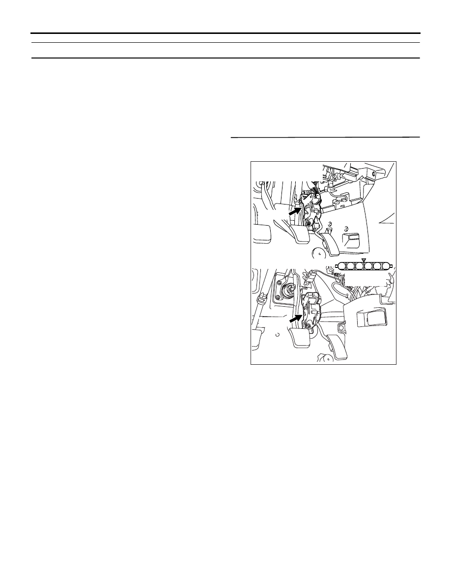
STEP 1. Connector check: C-102 accelerator 
pedal position connector

Q: Is the check result normal?

YES : 

Go to Step 2 .

NO : 

Repair or replace.

AK305627

1

6 5 4 3 2

Connector: C-102

AB

C-102 (B)

Harness side
connector

C-102 (B)

<L.H. drive vehicles>

<R.H. drive vehicles>

TROUBLESHOOTING

MULTIPORT FUEL INJECTION (MPI)

13A-268

STEP 2. Perform resistance measurement at 
C-102 accelerator pedal position sensor 
connector.

• Disconnect connector, and measure at harness 

side.

• Resistance between terminal No. 2 and earth.

OK: 2 

 or less

Q: Is the check result normal?

YES : 

Go to Step 6 .

NO : 

Go to Step 3 .

STEP 3. Connector check: C-113 engine-ECU 
<M/T> connector or engine-A/T-ECU <A/T> 
connector

Q: Is the check result normal?

YES : 

Go to Step 4 .

NO : 

Repair or replace.

AK305627

1

6 5 4 3 2

Connector: C-102

AB

C-102 (B)

Harness side
connector

C-102 (B)

<L.H. drive vehicles>

<R.H. drive vehicles>

AK305616AB

Connector: C-113

<L.H. drive vehicles>

<R.H. drive vehicles>

C-113 (GR)

C-113 (GR)

91

92

93

94

95

96

97

98

99

100

101

102

103

104

105

106

107

108

109

110

111

112

113

114

115

116

117

118

119

120

Harness side connector

TROUBLESHOOTING

MULTIPORT FUEL INJECTION (MPI)

13A-269

STEP 4. Check harness between C-102 (terminal 
No. 2) accelerator pedal position sensor 
connector and C-113 (terminal No. 91) 
engine-ECU <M/T> connector or engine-A/T-ECU 
<A/T> connector.

• Check earthing line for damage.

Q: Is the check result normal?

YES : 

Go to Step 5 .

NO : 

Repair.

STEP 5. Check the trouble symptoms

Q: Does trouble symptom persist?

YES : 

Replace engine-ECU <M/T> or 

engine-A/T-ECU <A/T>.

NO : 

Intermittent malfunction (Refer to GROUP 
00 

− How to Use 

Troubleshooting/Inspection Service Points 

P.00-5

).

STEP 6. Perform resistance measurement at 
C-102 accelerator pedal position sensor 
connector.

• Disconnect connector, and measure at harness 

side.

• Resistance between terminal No. 5 and earth.

OK: 2 

 or less

Q: Is the check result normal?

YES : 

Go to Step 9 .

NO : 

Go to Step 7 .

AK305627

1

6 5 4 3 2

Connector: C-102

AB

C-102 (B)

Harness side
connector

C-102 (B)

<L.H. drive vehicles>

<R.H. drive vehicles>

AK305616AB

Connector: C-113

<L.H. drive vehicles>

<R.H. drive vehicles>

C-113 (GR)

C-113 (GR)

91

92

93

94

95

96

97

98

99

100

101

102

103

104

105

106

107

108

109

110

111

112

113

114

115

116

117

118

119

120

Harness side connector

AK305627

1

6 5 4 3 2

Connector: C-102

AB

C-102 (B)

Harness side
connector

C-102 (B)

<L.H. drive vehicles>

<R.H. drive vehicles>

TROUBLESHOOTING

MULTIPORT FUEL INJECTION (MPI)

13A-270

STEP 7. Connector check: C-113 engine-ECU 
<M/T> connector or engine-A/T-ECU <A/T> 
connector

Q: Is the check result normal?

YES : 

Go to Step 8 .

NO : 

Repair or replace.

STEP 8. Check harness between C-102 (terminal 
No. 5) accelerator pedal position sensor 
connector and C-113 (terminal No. 96) 
engine-ECU <M/T> connector or engine-A/T-ECU 
<A/T> connector.

NOTE: Before checking harness, check intermediate 
connector C-116, and repair if necessary.

• Check earthing line for damage.

Q: Is the check result normal?

AK305616AB

Connector: C-113

<L.H. drive vehicles>

<R.H. drive vehicles>

C-113 (GR)

C-113 (GR)

91

92

93

94

95

96

97

98

99

100

101

102

103

104

105

106

107

108

109

110

111

112

113

114

115

116

117

118

119

120

Harness side connector

AK305627

1

6 5 4 3 2

Connector: C-102

AB

C-102 (B)

Harness side
connector

C-102 (B)

<L.H. drive vehicles>

<R.H. drive vehicles>

AK305616AB

Connector: C-113

<L.H. drive vehicles>

<R.H. drive vehicles>

C-113 (GR)

C-113 (GR)

91

92

93

94

95

96

97

98

99

100

101

102

103

104

105

106

107

108

109

110

111

112

113

114

115

116

117

118

119

120

Harness side connector


Content   ..  752  753  754  755   ..