Mitsubishi Grandis. Manual - part 749


  Index      Mitsubishi     Mitsubishi Grandis - service repair manual


Search            


Content   ..  747  748  749  750   ..


Mitsubishi Grandis. Manual - part 749


TROUBLESHOOTING

MULTIPORT FUEL INJECTION (MPI)

13A-247

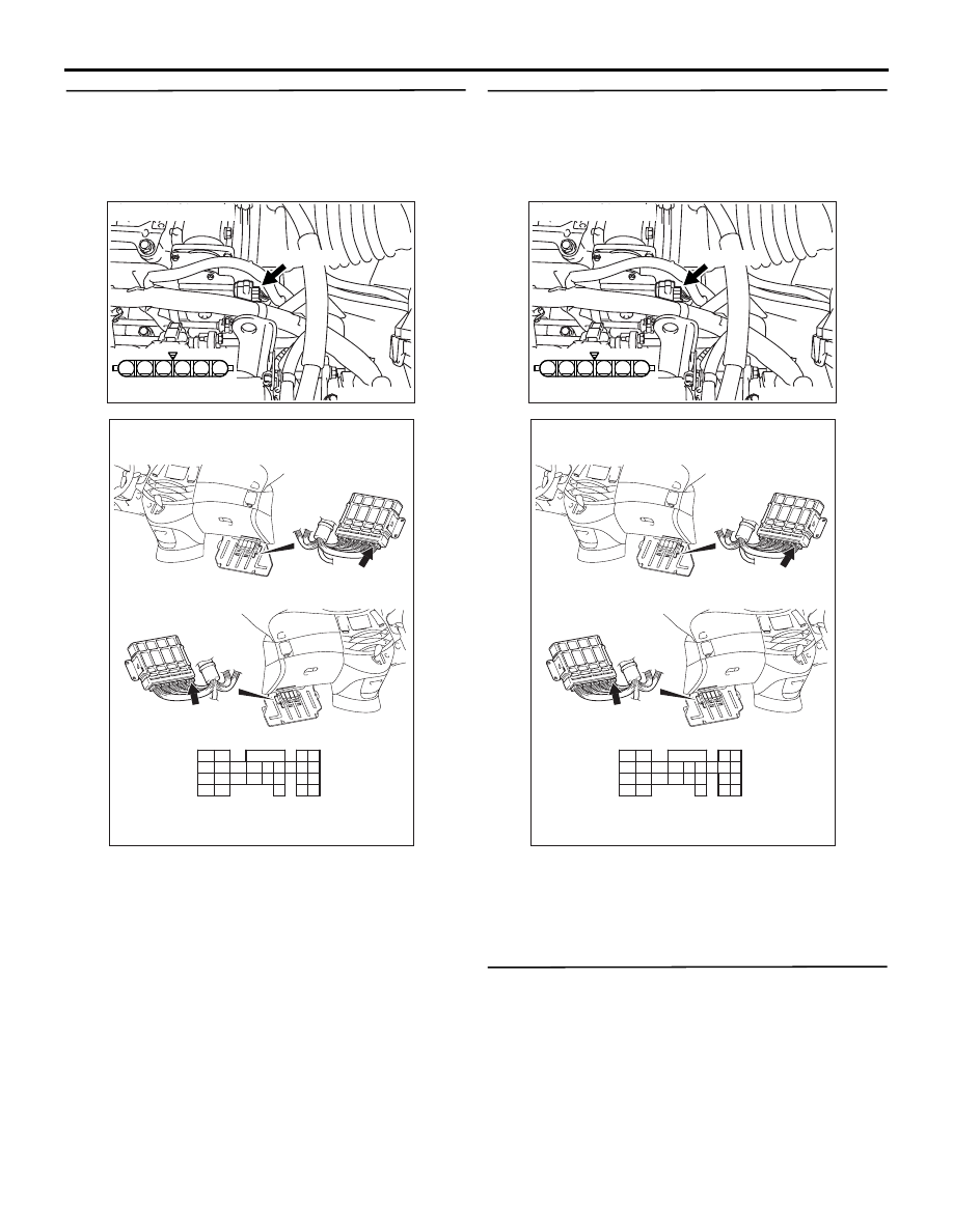
STEP 4. Check harness between B-06 (terminal 
No. 1) electronic-controlled throttle valve 
connector and C-114 (terminal No. 133) 
engine-ECU <M/T> connector or engine-A/T-ECU 
<A/T> connector.

• Check output line for short circuit.

Q: Is the check result normal?

YES : 

Go to Step 5 .

NO : 

Repair.

STEP 5. Check harness between B-06 (terminal 
No. 2) electronic-controlled throttle valve 
connector and C-114 (terminal No. 141) 
engine-ECU <M/T> connector or engine-A/T-ECU 
<A/T> connector.

• Check output line for short circuit.

Q: Is the check result normal?

YES : 

Go to Step 6 .

NO : 

Repair.

STEP 6. Check the trouble symptoms.

Q: Is the check result normal? 

YES : 

Replace engine-ECU <M/T> or 

engine-A/T-ECU <A/T>.

NO : 

Intermittent malfunction (Refer to GROUP 
00 

− How to Use 

Troubleshooting/Inspection Service Points 

P.00-5

).

AK300972

1

6 5 4 3 2

AC

Harness side connector

Connectors: B-06

B-06 (B)

AK305623AB

Connector: C-114

<L.H. drive vehicles>

<R.H. drive vehicles>

C-114 (GR)

C-114 (GR)

121

122

123

124

125

126

127

128

129

130

131

132

133

134

135

136

137

138

139

140

141

142

143

144

145

146

Harness side connector

TROUBLESHOOTING

MULTIPORT FUEL INJECTION (MPI)

13A-248

Code No. P2122: Accelerator Pedal Position Sensor (Main) Circuit Low Input

OPERATION

• A power voltage of 5 V is applied to the 

accelerator pedal position sensor (terminal No. 1) 
from the engine-ECU <M/T> or engine-A/T-ECU 
<A/T> (terminal No. 92).

• The power voltage is earthed to the engine-ECU 

<M/T> or engine-A/T-ECU <A/T> (terminal No. 
91) from the accelerator pedal position sensor 
(terminal No. 2).

• The sensor signal is inputted to the engine-ECU 

<M/T> or engine-A/T-ECU <A/T> (terminal No. 
114) from the accelerator pedal position sensor 
output terminal (terminal No. 3).

FUNCTION

• The accelerator pedal position sensor (main) 

outputs voltage which corresponds to the 
accelerator pedal depression.

• The engine-ECU <M/T> or engine-A/T-ECU 

<A/T> checks whether the voltage is within a 
specified range.

TROUBLE JUDGMENT

Check Condition

• Ignition switch is in ON position.

Judgment Criterion

• Accelerator pedal position sensor (main) output 

voltage is 0.2 volt or less for 0.3 second.

PROBABLE CAUSE

• Failed accelerator pedal position sensor

• Open/short circuit in accelerator pedal position 

sensor circuit or loose connector contact

• Failed engine-ECU <M/T>

• Failed engine-A/T-ECU <A/T>

AK305571

9192

939495

96979899

100

105

113114

115116117

118119120

106

107108109

110111112

101102103

104

6

1 2 3 4 5

AB

5 V

92

1

Accelerator
pedal
position
sensor
(main)

Y-G

GR

BR-W

Engine-ECU <M/T> or
engine-A/T-ECU <A/T>

114

91

3

2

Accelerator pedal position sensor (main) circuit

C-113

(MU803805)

C-102 

Wire colour code
B: Black  LG: Light green  G: Green  L: Blue  W: White  Y: Yellow  SB: Sky blue  BR: Brown  O: Orange  GR: Gray
R: Red  P: Pink  V: Violet

Hall IC

TROUBLESHOOTING

MULTIPORT FUEL INJECTION (MPI)

13A-249

DIAGNOSIS PROCEDURE

STEP 1. MUT-III data list

• Refer to Data List Reference Table 

P.13A-363

.

a. Item 78: Accelerator pedal position sensor 

(main)

Q: Is the check result normal?

YES : 

Intermittent malfunction (Refer to GROUP 

00 

− How to Use 

Troubleshooting/Inspection Service Points 

P.00-5

).

NO : 

Go to Step 2 .

STEP 2. Connector check: C-102 accelerator 
pedal position sensor connector

Q: Is the check result normal?

YES : 

Go to Step 3.

NO : 

Repair or replace.

STEP 3. Perform voltage measurement at C-102 
accelerator pedal position sensor connector.

• Disconnect connector, and measure at harness 

side.

• Ignition switch: ON 

• Voltage between terminal No. 1 and earth.

OK: 4.9 

 5.1 V

Q: Is the check result normal?

YES : 

Go to Step 7 .

NO : 

Go to Step 4 .

AK305627

1

6 5 4 3 2

Connector: C-102

AB

C-102 (B)

Harness side
connector

C-102 (B)

<L.H. drive vehicles>

<R.H. drive vehicles>

AK305627

1

6 5 4 3 2

Connector: C-102

AB

C-102 (B)

Harness side
connector

C-102 (B)

<L.H. drive vehicles>

<R.H. drive vehicles>

TROUBLESHOOTING

MULTIPORT FUEL INJECTION (MPI)

13A-250

STEP 4. Connector check: C-113 engine-ECU 
<M/T> connector or engine-A/T-ECU <A/T> 
connector

Q: Is the check result normal?

YES : 

Go to Step 5 .

NO : 

Repair or replace.

STEP 5. Check harness between C-102 (terminal 
No. 1) accelerator pedal position sensor 
connector and C-113 (terminal No. 92) 
engine-ECU <M/T> or engine-A/T-ECU <A/T> 
connector.

Q: Is the check result normal?

YES : 

Go to Step 6 .

NO : 

Repair.

AK305616AB

Connector: C-113

<L.H. drive vehicles>

<R.H. drive vehicles>

C-113 (GR)

C-113 (GR)

91

92

93

94

95

96

97

98

99

100

101

102

103

104

105

106

107

108

109

110

111

112

113

114

115

116

117

118

119

120

Harness side connector

AK305627

1

6 5 4 3 2

Connector: C-102

AB

C-102 (B)

Harness side
connector

C-102 (B)

<L.H. drive vehicles>

<R.H. drive vehicles>

AK305616AB

Connector: C-113

<L.H. drive vehicles>

<R.H. drive vehicles>

C-113 (GR)

C-113 (GR)

91

92

93

94

95

96

97

98

99

100

101

102

103

104

105

106

107

108

109

110

111

112

113

114

115

116

117

118

119

120

Harness side connector


Content   ..  747  748  749  750   ..