Mitsubishi Grandis. Manual - part 735
 

  Index      Mitsubishi     Mitsubishi Grandis - service repair manual


Search            


Content   ..  733  734  735  736   ..


Mitsubishi Grandis. Manual - part 735


TROUBLESHOOTING

MULTIPORT FUEL INJECTION (MPI)

13A-191

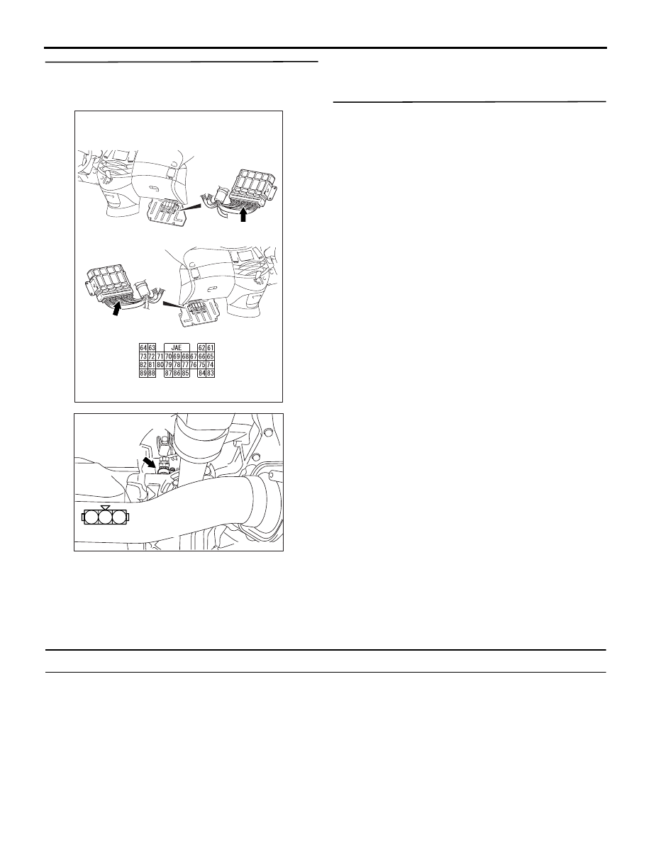
STEP 4.Check harness between C-112 (terminal 
No. 79) engine-ECU connector and B-107-1 
(terminal No. 3) Vehicle speed sensor connector.

NOTE: Before checking harness, check intermediate 
connector B-107, and repair if necessary.

• Check output line for open circuit and damage.

Q: Is the check result normal?

YES : 

Go to Step 5 .

NO : 

Repair.

STEP 5.Check the trouble symptoms.

Q: Does trouble symptom persist?

YES : 

 Replacing engine-ECU.

NO : 

Intermittent malfunction (Refer to GROUP 
00 - How to Use Troubleshooting/Inspection 
Service Points 

P.00-5

).

Code No. P0500: Vehicle Speed Signal System <A/T>

FUNCTION

• Receives the signal from the secondary speed 

sensor used for the A/T control and converts it to 
the vehicle speed signal, and then inputs it to the 
engine control system and the speedometer.

TROUBLE JUDGMENT

Check Conditions

• After 2 seconds pass from when the engine has 

completed the starting.

• The engine rpm is 2500 − 4000 r/min.

• Under the high load operation.

AK305617

Connector: C-112 

C-112 (GR)

C-112 (GR)

AB

Harness side connector

<R.H. drive vehicles>

<L.H. drive vehicles>

AK305620

1

2

3

AB

B-107-1 (B)

Connector: B-107-1

Harness side connector

TROUBLESHOOTING

MULTIPORT FUEL INJECTION (MPI)

13A-192

Judgment Criterion

• The sensor output voltage does not vary for 4 

seconds. (The pulse signal is not input.)

PROBABLE CAUSE

• Malfunction in the secondary speed sensor

• Open circuit, short or damage in the secondary 

speed sensor circuits or connection failure of the 
connector

• Malfunction in engine-A/T-ECU

DIAGNOSIS PROCEDURE

STEP 1. MUT-III other system diagnosis codes

Q: Is the diagnosis code output for A/T system?

YES : 

A/T system check (Refer to GROUP 

23-DIAGNOSIS CODE CLASSIFIED 
TABLE

P.23A-17

.)

NO : 

Go to STEP 2.

STEP 2. MUT-III diagnosis code

• Reconfirmation of the diagnosis code.

Q: Is the diagnosis code output?

YES : 

 Replacement of Engine-A/T-ECU.

NO : 

Intermittent malfunction (Refer to GROUP 
00 

− How to Use 

Troubleshooting/Inspection Service Points 

P.00-5

).

Code No. P0505: Idle Speed Control (ISC) System

FUNCTION

• The amount of air taken in during idling is 

regulated by the opening and closing of the 
throttle valve.

• The engine-ECU <M/T> or engine-A/T-ECU 

<A/T> checks the difference between the actual 
engine speed and the target engine speed.

TROUBLE JUDGMENT

Check Conditions

• The vehicle speed has reached 1.5 km/h or more 

at least once.

• During the closed-loop idle speed control.

Judgment Criterion

•  The actual idle speed is higher than the target 

idle speed by 300 r/min or more for 10 seconds.

Check Conditions

• The vehicle speed has reached 1.5 km/h or more 

at least once.

• During the closed-loop idle speed control.

• The highest ambient temperature at the last drive 

is 45

°C or less.

•  The engine coolant temperature is approx. 77°C 

or higher.

•  The battery voltage is 10 V or more.

•  The intake air temperature is -10°C or higher.

Judgment Criterion

•  The actual idle speed is higher than the target 

idle speed by 200 r/min or more for 10 seconds.

Check Conditions

• During the closed-loop idle speed control

• The engine coolant temperature is approx. 77°C 

or higher.

•  The battery voltage is 10 V or more.

• The power steering switch is in OFF position.

• The charging efficiency is 40 % or less.

•  The intake air temperature is -10°C or higher.

Judgment Criterion

• The actual idle speed is lower than the target idle 

speed by 100 r/min or more for 10 seconds.

PROBABLE CAUSE

• Throttle valve area is dirty.

• Intake system vacuum leak.

• Failed engine-ECU <M/T>

• Failed engine-A/T-ECU <A/T>

STEP 1: MUT-III diagnosis code

Q: Diagnosis code set?

YES : 

Inspection chart for diagnosis code (Refer 

to 

P.13A-20

.)

NO : 

Go to Step 2 .

STEP 2: Check throttle body (throttle valve 
portion) for contamination.

Q: Is the check result normal?

YES : 

Go to Step 3 .

NO : 

Clean throttle body (throttle valve portion) 
(Refer to 

P.13A-383

).

TROUBLESHOOTING

MULTIPORT FUEL INJECTION (MPI)

13A-193

STEP 3. Check air intake from intake hose and 
inlet manifold.

Q: Is the check result normal?

YES : 

Go to Step 4 .

NO : 

Repair.

STEP 4. Check the trouble symptoms.

Q: Does trouble symptom persist?

YES : 

Replace engine-ECU <M/T> or 

engine-A/T-ECU <A/T>.

NO : 

Intermittent malfunction (Refer to GROUP 
00 

− How to Use 

Troubleshooting/Inspection Service Points 

P.00-5

).

Code No. P0513: Immobilizer Malfunction

OPERATION

• The signals are sent and received between 

engine-ECU <M/T> or engine-A/T-ECU <A/T> 
(terminal No. 65) and immobilizer-ECU (terminal 
No. 7).

FUNCTION

• Engine-ECU <M/T> or engine-A/T-ECU <A/T> 

sends or receives the control signals to or from 
immobilizer-ECU to certify the ignition key.

NOTE: 

.

•

If the registered ignition keys are close each 
other when starting the engine, radio 
interference may cause this code to be 
displayed.

•

This code may be displayed when registering 
the key encrypted code.

AK305566

1

2

3 4 5 6 7

61
656667686970 717273
74757677787980 8182
8384

858687

8889

62

6364

65

7

16

C-308

MU801547

C-17

Engine-ECU <M/T> or
engijne-A/T-ECU <A/T>

Immobilizer-ECU circuit

Immobilizer-ECU

AB

W-V

W-V

C-112

(MU803804)

Wire colour code
B: Black  LG: Light green  G: Green  L: Blue  W: White  Y: Yellow  SB: Sky blue  BR: Brown  O: Orange  GR: Gray
R: Red  P: Pink  V: Violet

TROUBLESHOOTING

MULTIPORT FUEL INJECTION (MPI)

13A-194

TROUBLE JUDGMENT

Check Condition

• Ignition switch is in "ON" position.

Judgment Criterion

• When the communication error between 

engine-ECU <M/T> or engine-A/T-ECU <A/T> 
and the immobilizer-ECU continues for 2 seconds 
or more.

PROBABLE CAUSE

• Open/short circuit in immobilizer system circuit or 

loose connector contact

• Failed immobilizer-ECU

• Failed engine-ECU <M/T>

• Failed engine-A/T-ECU <A/T>

DIAGNOSIS PROCEDURE

STEP 1. Connector check: C-308 
immobilizer-ECU connector and C-112 
engine-ECU <M/T> connector or engine-A/T-ECU 
<A/T> connector.

Q: Is the check result normal? 

YES : 

Go to Step 2 .

NO : 

Repair or replace.

AK305621

2

7 6 5 4 3

1

AB

C-308

Harness side connector

Connector: C-308

AK305617

Connector: C-112 

C-112 (GR)

C-112 (GR)

AB

Harness side connector

<R.H. drive vehicles>

<L.H. drive vehicles>


Content   ..  733  734  735  736   ..