Mitsubishi Grandis. Manual - part 690


  Index      Mitsubishi     Mitsubishi Grandis - service repair manual


Search            


Content   ..  688  689  690  691   ..


Mitsubishi Grandis. Manual - part 690


TROUBLESHOOTING

MULTIPORT FUEL INJECTION (MPI)

13A-11

TROUBLESHOOTING

DIAGNOSIS TROUBLESHOOTING FLOW

M1131150000999

Refer to 

P.00-5

, GROUP 00 

− How to Use 

Troubleshooting/Inspection Service Points.

DIAGNOSIS FUNCTION

M1131155500609

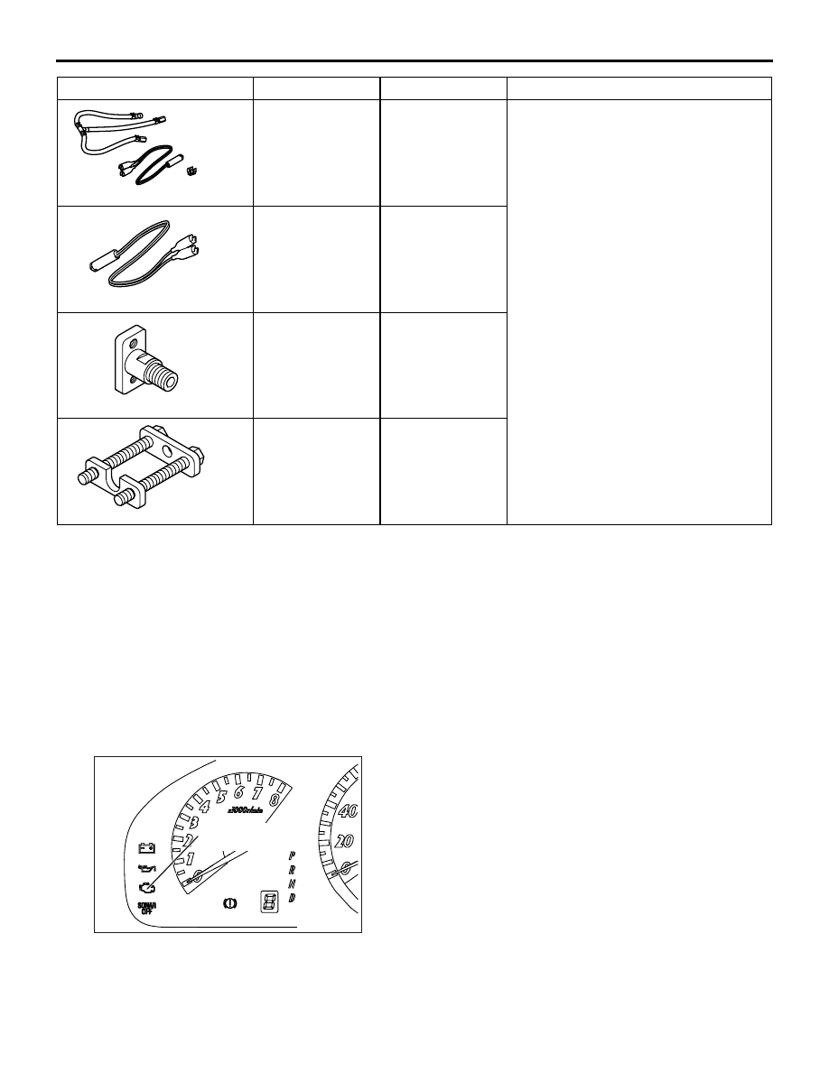
ENGINE WARNING LAMP (CHECK 
ENGINE LAMP)

If an abnormality occurs in any of the following items 
related to the Multipoint Fuel Injection (MPI) system, 
the engine warning lamp will illuminate.
If the lamp remains illuminated or if the lamp 
illuminates while the engine is running, check the 
diagnosis code output.

MD998706

Injector test set

Checking the spray condition of 
injectors

MB991607

Injector test 
harness

MD998741

Injector test 
adaptor

MB991976

Injector test 
holder assembly

Tool

Number

Name

Use

MD998706

MB991607

MD998741

MB991976

AK305640

Engine warning lamp
(check engine lamp)

AB

TROUBLESHOOTING

MULTIPORT FUEL INJECTION (MPI)

13A-12

ENGINE WARNING LAMP INSPECTION ITEMS

Code No.

Diagnosis item

Engine-ECU <M/T> or engine-A/T-ECU <A/T>

P0100

Air flow sensor system

P0105

Barometric pressure sensor system

P0110

Intake air temperature sensor system

P0115

Engine coolant temperature sensor system

P0122*

Throttle position sensor (main) circuit low input

P0123*

Throttle position sensor (main) circuit high input

P0125*

Feedback system monitor

P0130

Cylinder 1, 4 oxygen sensor (front) system

P0135

Cylinder 1, 4 oxygen sensor (front) heater system

P0136

Cylinder 1, 4 oxygen sensor (rear) system

P0141

Cylinder 1, 4 oxygen sensor (rear) heater system

P0150

Cylinder 2, 3 oxygen sensor (front) system

P0155

Cylinder 2, 3 oxygen sensor (front) heater system

P0156

Cylinder 2, 3 oxygen sensor (rear) system

P0161

Cylinder 2, 3 oxygen sensor (rear) heater system

P0170

Abnormal fuel system (cylinder 1,4)

P0173

Abnormal fuel system (cylinder 2,3)

P0201

No.1 injector system

P0202

No.2 injector system

P0203

No.3 injector system

P0204

No.4 injector system

P0222*

Throttle position sensor (sub) circuit low input

P0223*

Throttle position sensor (sub) circuit high input

P0300*

Random/multiple cylinder misfire detected

P0301*

No.1 cylinder misfire detected

P0302*

No.2 cylinder misfire detected

P0303*

No.3 cylinder misfire detected

P0304*

No.4 cylinder misfire detected

P0325

Detonation sensor system

P0335

Crank angle sensor system

P0340

Camshaft position sensor system

P0403

Exhaust gas recirculation control system

P0421

Warm up catalyst malfunction (cylinder 1,4)

P0431

Warm up catalyst malfunction (cylinder 2,3)

P0443

Purge control solenoid valve system

P0500

Vehicle speed sensor system <M/T>

P0500

Vehicle speed signal system <A/T>

P0505

Idle speed control (ISC) system

TROUBLESHOOTING

MULTIPORT FUEL INJECTION (MPI)

13A-13

P0513

Immobilizer malfunction

P0551*

Power steering fluid pressure sensor system

P0603

EEP ROM system

P0606*

Engine-ECU <M/T> or engine-A/T-ECU <A/T> main processor malfunction

P0622

Alternator FR terminal system

P0638*

Throttle valve control servo circuit range/performance problem

P0642*

Throttle position sensor power supply

P0657*

Throttle valve control servo relay circuit malfunction

P0705

Inhibitor switch system

P0710

A/T fluid temperature sensor system

P0715*

Input shaft speed sensor system

P0720*

Output shaft speed sensor system

P0740*

Torque converter clutch solenoid valve system

P0750*

Low-reverse solenoid valve system

P0755*

Underdrive solenoid valve system

P0760*

Second solenoid valve system

P0765*

Overdrive solenoid valve system

P1021

Oil control valve system

P1602*

Communication malfunction (between engine-ECU <M/T> or engine-A/T-ECU <A/T> 
main processor and system LSI)

P1603*

Battery backup circuit malfunction

P1751*

A/T control relay system

P2100*

Throttle valve control servo circuit (open)

P2101*

Throttle valve control servo magneto malfunction

P2102*

Throttle valve control servo circuit (shorted low)

P2103*

Throttle valve control servo circuit (shorted high)

P2122*

Accelerator pedal position sensor (main) circuit low input

P2123*

Accelerator pedal position sensor (main) circuit high input

P2127*

Accelerator pedal position sensor (sub) circuit low input

P2128*

Accelerator pedal position sensor (sub) circuit high input

P2135*

Throttle position sensor (main and sub) range/performance problem

P2138*

Accelerator pedal position sensor (main and sub) range/performance problem

P2173*

Abnormal intake air amount

U1108*

Combination meter time-out

Code No.

Diagnosis item

TROUBLESHOOTING

MULTIPORT FUEL INJECTION (MPI)

13A-14

NOTE: 

.

If the engine warning lamp illuminates because of a malfunction of the engine-ECU <M/T> or 
engine-A/T-ECU <A/T>, communication between MUT-III and the engine-ECU <M/T> or engine-A/T-ECU 
<A/T> is impossible. In this case, the diagnosis code cannot be read.

After the engine-ECU <M/T> or engine-A/T-ECU <A/T> has detected a malfunction, the engine warning 
lamp illuminates when the engine is next turned on and the same malfunction is re-detected.However, for 
items marked with a "*" in the diagnosis code number column, the engine warning lamp illuminates only 
on the first detection of the malfunction.

After the engine warning lamp illuminates, it will be switched off under the following conditions.

When the engine-ECU <M/T> or engine-A/T-ECU <A/T> monitored the power train malfunction three 
times* met set condition requirements, it detected no malfunction.

*: In this case, "one time" indicates from engine start to stop.

For misfiring malfunction, when driving conditions (engine speed, engine coolant temperature, etc.) 
are similar to those when the malfunction was first recorded.

Sensor 1 indicates, the sensor mounted at a position closest to the engine, and sensor 2 indicates the 
sensor mounted at the position second closest to the engine.

METHOD OF READING AND ERASING 
DIAGNOSIS CODES

Refer to 

P.00-5

, GROUP 00 

− How to Use 

Troubleshooting/Inspection Service Points.

DIAGNOSIS USING DIAGNOSIS 2 MODE

1. Switch the diagnosis mode of the engine control 

unit to DIAGNOSIS 2 mode using the MUT-III.

2. Carry out a road test.
3. Take a reading of the diagnosis code and repair 

the problem location.

4. Turn the ignition switch to OFF and then back to 

ON again.

NOTE: By turning the ignition switch to OFF, the 

engine-ECU <M/T> or engine-A/T-ECU <A/T> 
will switch the diagnosis mode from DIAGNOSIS 
2 mode to DIAGNOSIS 1 mode.

5. Erase the diagnosis codes.

INSPECTION USING MUT-III DATA LIST 
AND ACTUATOR TESTING

1. Carry out inspection by means of the data list and 

the actuator test function, if there is an 
abnormality, check and repair the chassis harness 
and components.

2. After repairing, re-check using the MUT-III and 

check that the abnormal input and output have 
returned to normal as a result of the repairs.

3. Erase the diagnosis code memory.
4. Remove the MUT-III, and then start the engine 

again and carry out a road test to confirm that the 
problem has disappeared.

FREEZE FRAME DATA

When the engine-ECU <M/T> or engine-A/T-ECU 
<A/T> detects a malfunction and stores a diagnosis 
code, it also stores a current status of the engine. 
This function is called "Freeze frame data". By 
analyzing this "Freeze frame" data with the MUT-III, 
an effective troubleshooting can be performed.
The display items of freeze frame data are shown 
below.

DISPLAY ITEM LIST

Item No.

Data

Unit

12

Air flow sensor

gm/s

13

Intake air temperature sensor

°C

21

Engine coolant temperature sensor

°C

22

Crank angle sensor

r/min

24

Vehicle speed

km/h

44

Ignition advance

deg


Content   ..  688  689  690  691   ..