Mitsubishi Grandis. Manual - part 664


  Index      Mitsubishi     Mitsubishi Grandis - service repair manual


Search            


Content   ..  662  663  664  665   ..


Mitsubishi Grandis. Manual - part 664


OIL PAN AND OIL PUMP

ENGINE OVERHAUL

11B-51

>>K<< OIL PAN INSTALLATION 

CAUTION

Do not apply FIPG over remaining old FIPG. 
Doing so could result in oil leakage.
1. Thoroughly remove old FIPG from the gasket 

surfaces of the cylinder block and oil pan.

CAUTION

Too much FIPG will squeeze out, blocking 
coolant or oil passages, while too thin a bead 
could result in leakage.
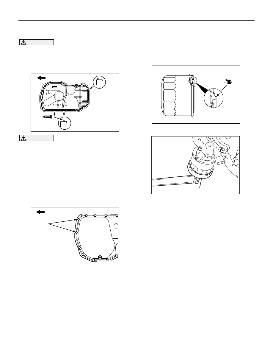
2. Apply a 4 mm diameter bead of FIPG to the flange 

surface all around the oil pan.

Specified sealant:

Mitsubishi Genuine Part No.MD970389 or 

equivalent

NOTE: In the grooved areas on the oil pan flange, 
apply FIPG bead along the center of the groove.

3. Install the shorter bolts in the locations indicated 

in the drawing.

>>L<< OIL FILTER INSTALLATION

1. Clean the installation surface of the filter bracket.

2. Apply engine oil to the o-ring of the oil filter.

3. Using general service tool, Install the oil filter to 

the bracket and tighten it to the specified torque.

Tightening torque

Part number MD356000 filter: 14 

± 2 Nm

Other Mitsubishi Genuine filter: 17 

± 3 Nm

4. If a torque wrench cannot be used use the 

following procedure:
(1) Screw in the oil filter until its o-ring contacts 

the oil filter bracket.

(2) Tighten the oil filter as follows:

Mitsubishi Genuine filter: 3/4 turn

AK202694

Timing belt side

Bolt hole 
area

Grooved
area

AB

AK202693

Timing belt side

M6 × 8

AD

AK301069AD

AK300186

General service tool

AD

OIL PAN AND OIL PUMP

ENGINE OVERHAUL

11B-52

>>M<< DRAIN PLUG GASKET 
INSTALLATION

CAUTION

If the gasket is installed in the wrong direction, 
oil leaks will occur.
Install the drain plug gasket in the direction shown.

INSPECTION

M1113008200342

FRONT CASE

1. Check the oil passage for clogging. Clean if 

necessary.

2. Check the left counterbalance shaft front bearing 

for wear, damage and seizure. If the bearing is 
damaged, replace the front case.

3. Check the front case for cracks and other 

damage.
Replace cracked or damaged front case.

OIL SEAL

1. Check the oil seal lip for wear and damage. 

Replace the oil seal if necessary.

2. Check the oil seal lip for deterioration. Replace 

the oil seal if necessary.

COUNTERBALANCE SHAFT

1. Check the oil holes for clogging and clean if 

necessary.

2. Check the journal for seizure, damage and 

contact with bearing. If there is anything wrong 
with the journal, replace the counterbalance shaft, 
bearing or front case assembly if required.

OIL PUMP

1. Assemble the oil pump gears to the front case and 

rotate it to ensure smooth rotation with no 
looseness.

2. Ensure that there is no ridge wear on the contact 

surface between the front case and the gear 
surface of the oil pump cover.

3. Check the side clearance.

Standard value:

Drive gear 0.08 

 0.14 mm

Driven gear 0.06 

 0.12 mm

AK300601AF

Drain plug

Oil pan

Gasket

Oil pan 
side

AK300187

AK300188

OIL PAN AND OIL PUMP

ENGINE OVERHAUL

11B-53

OIL LEVEL SENSOR

Put the oil level sensor in oil, then move the float 
up and down with the oil at a temperature either 
lower than 40

°C or higher than 80°C, and check 

for continuity.

40

°C

80

°C

AK304606AB

Float position

Switch ON/OFF

Condition when down

ON (continuity)

Condition when up

ON (continuity)

Float position

Switch ON/OFF

Condition when down

OFF (no continuity)

Condition when up

ON (continuity)

PISTON AND CONNECTING ROD

ENGINE OVERHAUL

11B-54

PISTON AND CONNECTING ROD

REMOVAL AND INSTALLATION

M1113008400733

REMOVAL SERVICE POINTS
<<A>>CONNECTING ROD CAP 
REMOVAL

AK301260AE

1

2

3

4

5

6

7
8

9

10

11

12

20 ± 2 N·m

→ + 90˚ to 94˚

Apply engine oil to
all moving parts
before installation.

Removal steps

>>G<<

1. Nut

<<A>> >>F<<

2. Connecting rod cap

>>D<<

3. Connecting rod bearing

>>E<<

4. Piston and connecting rod assembly

>>D<<

5. Connecting rod bearing

>>C<<

6. Piston ring No. 1

>>C<<

7. Piston ring No. 2

>>B<<

8. Oil ring

<<B>> >>A<<

9. Piston pin
10.Piston
11.Connecting rod
12.Bolt

AK202812

Cylinder 
number

AB


Content   ..  662  663  664  665   ..