Mitsubishi Grandis. Manual - part 634
ON-VEHICLE SERVICE
ENGINE MECHANICAL
11A-13
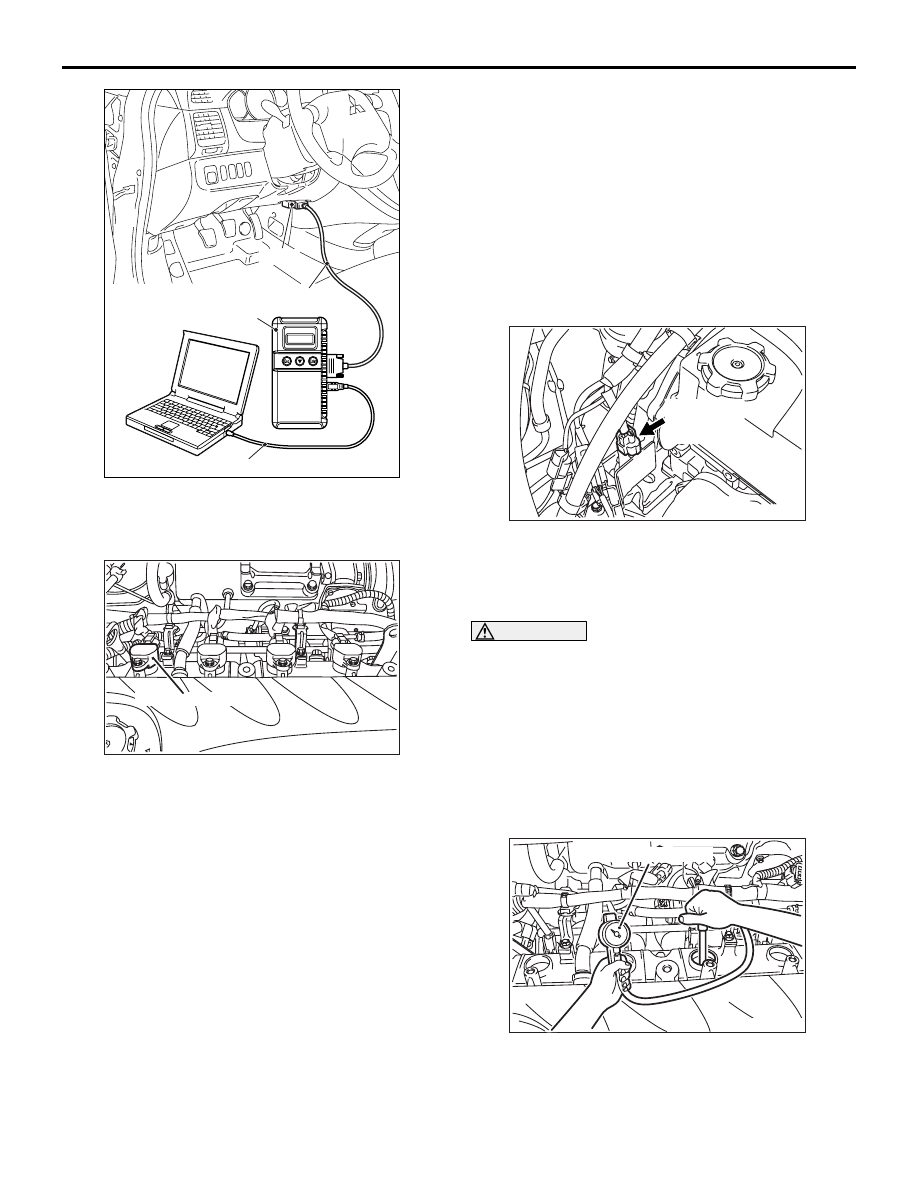
2. Turn the ignition switch to the "LOCK" (OFF)
position and then connect the MUT-III to the
diagnosis connector.
3. Set the timing light to the power supply line
(terminal No.1) of the ignition coil No.1.
NOTE: The power supply line is looped and also
longer than the other ones.
4. Start the engine and let it run at idle.
5. Check that ignition timing is at the standard value.
Standard value: approximately 10
° BTDC
6. Run the engine at 2,500 r/min for 2 minutes.
7. Set the CO, HC tester.
8. Check the CO contents and the HC contents at
idle.
Standard value
CO contents: 0.5 % or less
HC contents: 100 ppm or less
9. If there is a deviation from the standard value,
inspect the MPI system (Refer to
GROUP 13A
− Troubleshooting − Inspection
Chart for Diagnosis Code).
10.Turn the ignition switch to the "LOCK" (OFF)
position and then remove the MUT-III.
COMPRESSION PRESSURE CHECK
M1111002600722
1. Before inspection, set the vehicle to the
pre-inspection condition.
2. Remove all of the ignition coils and spark plugs.
3. Disconnect the crank angle sensor connector.
NOTE: Doing this will prevent the
engine-ECU<M/T> or engine-A/T-ECU<A/T> from
carrying out ignition and fuel injection.
WARNING
Keep away from the spark plug hole when
cranking. If compression is measured with
water, oil, fuel, etc., that has come from
cracks inside the cylinder, these materials
will become heated and will gush out from
the spark plug hole, which is dangerous.
4. Cover the spark plug hole with a shop towel etc.,
and after the engine has been cranked, check that
no foreign material is adhering to the shop towel.
5. Set compression gauge to one of the spark plug
holes.
6. Crank the engine with the throttle valve fully open
and measure the compression pressure.
AC302297
AC310120
AB
MB991827
16-pin
MB991910
MB991824
AK305596AB
No. 1 Ignition coil
AK303421AB
Crank angle
sensor
connector
AK204360
Compression gauge
AE