Mitsubishi Grandis. Manual - part 616


  Index      Mitsubishi     Mitsubishi Grandis - service repair manual


Search            


Content   ..  614  615  616  617   ..


Mitsubishi Grandis. Manual - part 616


DIAGNOSIS

CONTROLLER AREA NETWORK (CAN)

54D-562

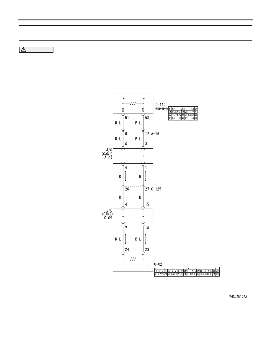
Diagnostic Item 23: Diagnose the lines from the main bus line to the engine-ECU <M/T> or 
engine-A/T-ECU <A/T>.

CAUTION

When servicing a CAN bus line, earth yourself by 
touching a metal object such as an unpainted 
water pipe. If you fail to do, a component 
connected to the CAN bus line may be broken.

TROUBLE JUDGMENT

If the MUT-III cannot receive any signal from the 
engine-ECU <M/T> or engine-A/T-ECU <A/T>, CAN 
bus line connector(s) are broken or an open circuit 
has occurred.

COMMENTS ON TROUBLE SYMPTOM

Connector(s), wiring harness in the CAN bus lines, 
the engine-ECU <M/T> or engine-A/T-ECU <A/T> 
may be defective.

ENGINE-ECU<M/T>
ENGINE·A/T-ECU<A/T>

COMBINATION
METER

Wire colour code
B : Black     LG : Light green     G : Green     L : Blue     W : White     Y : Yellow     SB : Sky blue
BR : Brown     O : Orange     GR : Gray     R : Red     P : Pink     V : Violet

DIAGNOSIS

CONTROLLER AREA NETWORK (CAN)

54D-563

POSSIBLE CAUSES

• Damaged harness wires and connectors

• Malfunction of the engine-ECU <M/T> or 

engine-A/T-ECU <A/T>

DIAGNOSTIC PROCEDURE

STEP 1. Connector check: A-07 joint connector 
(CAN1) and A-16 intermediate connector
NOTE: When checking A-07 joint connector (CAN1), 
disassemble and check the engine compartment 
relay box by referring to 

P.54D-616

.

CAUTION

The strand end of the twist wire should be within 
10 cm from the connector. For details refer to 

P.54D-8

.

When checking the joint connector, ensure that its 
wiring harness side is not damaged.

Q: Is the check result normal?

YES : 

Go to Step 2 .

NO : 

Repair a defective connector or replace the 
joint connector (front wiring harness 
assembly).

STEP 2. Resistance measurement at A-07 joint 
connector (CAN1) and A-16 intermediate 
connector.
NOTE: When checking A-07 joint connector (CAN1), 
disassemble and check the engine compartment 
relay box by referring to 

P.54D-616

.

CAUTION

A digital multimeter should be used. For details 
refer to 

P.54D-8

.

CAUTION

The test wiring harness should be used. For 
details refer to 

P.54D-8

.

(1) Disconnect the joint connector (CAN1) and the 

intermediate connector, and measure at the 
wiring harness side.

AC302572AD

Connector: A-07

Harness side

AC310403

AC

Connector: A-16 <LHD>

A-16 (B)

AC310398

AC

Connector: A-16 <RHD>

A-16 (B)

AC302572AD

Connector: A-07

Harness side

AC310403

AC

Connector: A-16 <LHD>

A-16 (B)

AC310398

AC

Connector: A-16 <RHD>

A-16 (B)

DIAGNOSIS

CONTROLLER AREA NETWORK (CAN)

54D-564

(2) Ignition switch: OFF (LOCK)

CAUTION

When measuring the resistance, disconnect the 
negative battery terminal. For details refer to 

P.54D-8

.

(3) Ensure that the negative battery terminal is 

disconnected.

(4) Continuity between A-07 joint connector (CAN1) 

terminal No.3 and A-16 intermediate connector 

terminal No.12

OK: 2 

 or less

(5) Continuity between A-07 joint connector (CAN1) 

terminal No.6 and A-16 intermediate connector 
terminal No.6

OK: 2 

 or less

CAUTION

Strictly observe the specified wiring harness 
repair procedure. For details refer to 

P.54D-8

.

Q: Is the check result normal?

YES : 

<All the voltages measure 2 

Ω or less> Go 

to Step 3   .

NO : 

<Either or all of the resistances measure 
more than 2 

Ω> Repair the wiring harness 

between joint connector (CAN1) and the 
intermediate connector.

AC312553

AC312553

Test harness

AQ

Harness side: A-07

Female side: A-16

Test
harness

AC312553

AC312553 AR

Harness side: A-07

Female side: A-16

Test
harness

Test
harness

DIAGNOSIS

CONTROLLER AREA NETWORK (CAN)

54D-565

STEP 3. Connector check: C-112 engine-ECU 
<M/T> or engine-A/T-ECU <A/T> connector

CAUTION

The strand end of the twist wire should be within 
10 cm from the connector. For details refer to 

P.54D-8

.

Q: Is the check result normal?

YES : 

Go to Step 4 .

NO : 

Repair a defective connector or replace the 
joint connector.

STEP 4. Resistance measurement at A-07 
intermediate connector and C-112 engine-ECU 
<M/T> or engine-A/T-ECU <A/T> connector.

CAUTION

A digital multimeter should be used. For details 
refer to 

P.54D-8

.

CAUTION

The test wiring harness should be used. For 
details refer to 

P.54D-8

.

(1) Disconnect the engine-ECU <M/T> or 

engine-A/T-ECU <A/T> connector and the 
intermediate connector, and measure at the 
wiring harness side.

(2) Ignition switch: OFF (LOCK)

CAUTION

When measuring the resistance, disconnect the 
negative battery terminal. For details refer to 

P.54D-8

.

(3) Ensure that the negative battery terminal is 

AC310615

AS

Harness side

Connector: C-112 <LHD>

C-112 (GR)

61

62

63

64

65

66

67

68

69

70

71

72

73

74

75

76

77

78

79

80

81

82

83

84

85

86

87

88

89

AC310628AW

Harness side

Connector: C-112 <RHD>

C-112 (GR)

61

62

63

64

65

66

67

68

69

70

71

72

73

74

75

76

77

78

79

80

81

82

83

84

85

86

87

88

89

AC302572AD

Connector: A-07

Harness side

AC310615

AS

Harness side

Connector: C-112 <LHD>

C-112 (GR)

61

62

63

64

65

66

67

68

69

70

71

72

73

74

75

76

77

78

79

80

81

82

83

84

85

86

87

88

89

AC310628AW

Harness side

Connector: C-112 <RHD>

C-112 (GR)

61

62

63

64

65

66

67

68

69

70

71

72

73

74

75

76

77

78

79

80

81

82

83

84

85

86

87

88

89


Content   ..  614  615  616  617   ..