Mitsubishi Grandis. Manual - part 608


  Index      Mitsubishi     Mitsubishi Grandis - service repair manual


Search            


Content   ..  606  607  608  609   ..


Mitsubishi Grandis. Manual - part 608


DIAGNOSIS

CONTROLLER AREA NETWORK (CAN)

54D-530

STEP 6. MUT-III CAN bus diagnostics (C-02 
combination meter connector disconnected)

(1) Disconnect the combination meter connector, 

and diagnose by using the MUT-III.

(2) Check that the MUT-III indications correspond to 

the illustration.

Q: Is the check result normal?

YES : 

<MUT-III indications correspond to the 

illustration> Go to Step 7 .

NO : 

<MUT-III indications do not correspond to 
the illustration> Go to Step 8 .

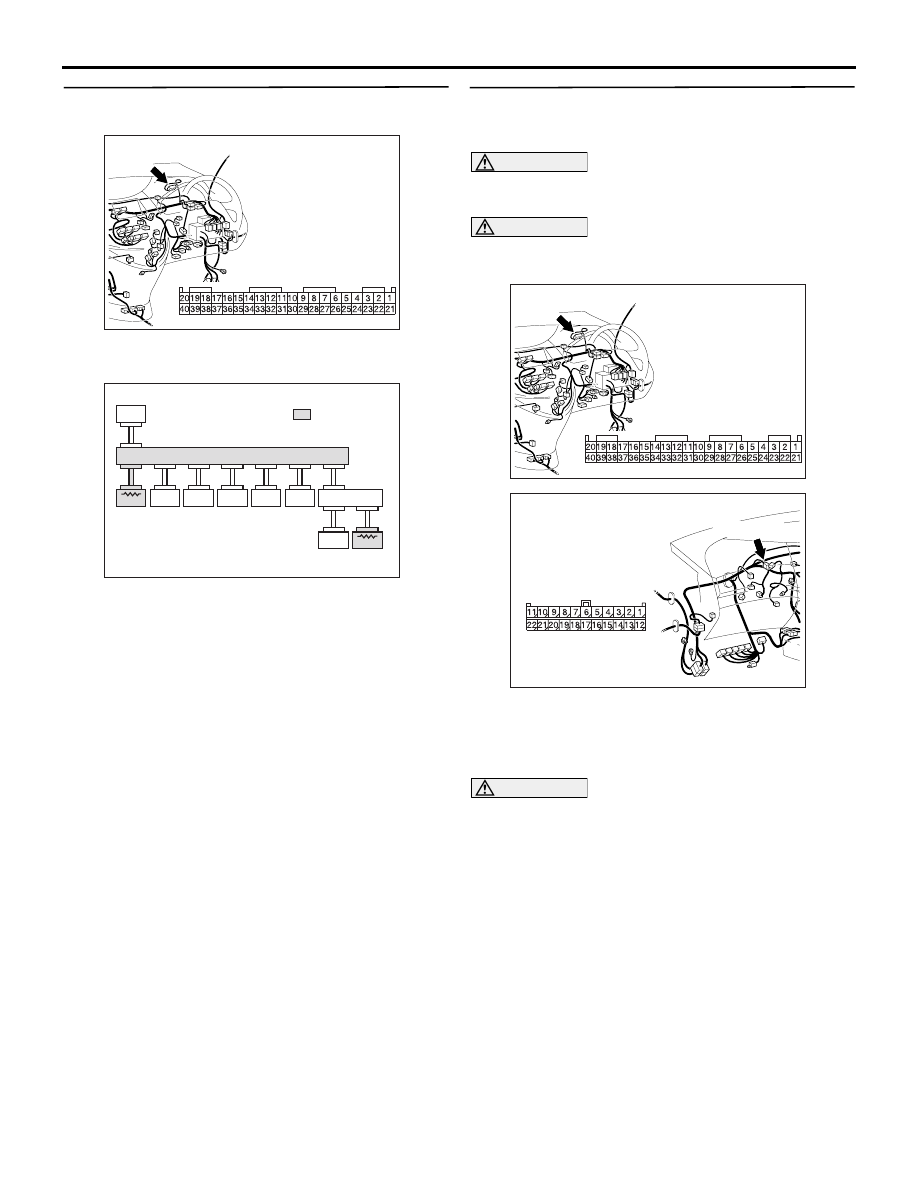
STEP 7. Resistance measurement at C-09 joint 
connector (CAN2) and C-02 combination meter 
connector.

CAUTION

A digital multimeter should be used. For details 
refer to 

P.54D-8

.

CAUTION

The test wiring harness should be used. For 
details refer to 

P.54D-8

.

(1) Disconnect the joint connector (CAN2) and the 

combination meter connector, and measure at 
the wiring harness side.

(2) Ignition switch: OFF (LOCK)

CAUTION

When measuring the resistance, disconnect the 
negative battery terminal. For details refer to 

P.54D-8

.

(3) Ensure that the negative battery terminal is 

AC310631AX

Connector: C-02 <RHD>

Harness side

C-02

AC309834

MUT

J/C (2)

METER

ETAC S

J/C (1)

ASC -ECU

ENG/AT-ECU

A/C -ECU

SRS-ECU

STR. A .

SNSR

C. DISPL AY

AD

 : Red section 

   on screen

AC310631AX

Connector: C-02 <RHD>

Harness side

C-02

AC310628AY

Connector: C-09 <RHD>

C-09 (GR)

Harness side

DIAGNOSIS

CONTROLLER AREA NETWORK (CAN)

54D-531

disconnected.

(4) Continuity between C-09 joint connector (CAN2) 

terminal No.6 and C-02 combination meter 
connector terminal No.24

OK: 2 

 or less

(5) Continuity between C-09 joint connector (CAN2) 

terminal No.17 and C-02 combination meter 

connector terminal No.23

OK: 2 

 or less

CAUTION

Strictly observe the specified wiring harness 
repair procedure. For details refer to 

P.54D-8

.

Q: Are the check results normal?

YES : 

<All the resistances measure 2 

Ω or less> 

Power supply to the combination meter may 
be suspected. Diagnose the combination 
meter. Refer to 

P.54A-55

.

NO : 

<Either or all of the resistances measure 
more than 2 

Ω> Repair the wiring harness 

between joint connector (CAN2) and the 
combination meter connector.

STEP 8. Connector check: C-106 A/C-ECU 
connector

CAUTION

The strand end of the twist wire should be within 
10 cm from the connector. For details refer to 

P.54D-8

.

Q: Is the check result normal?

YES : 

Go to Step 9 .

NO : 

Repair the defective connector.

STEP 9. MUT-III CAN bus diagnostics (C-106 
A/C-ECU connector disconnected)

(1) Disconnect the A/C-ECU connector, and 

AC312553  AJ

Harness side: C-09

Test
harness

Harness side: C-02

Test
harness

AC312553  AL

Harness side: C-09

Harness side: C-02

Test
harness

Test
harness

AC310631AB

Connectors: C-106 <RHD>

Harness side

AC310631AB

Connectors: C-106 <RHD>

Harness side

DIAGNOSIS

CONTROLLER AREA NETWORK (CAN)

54D-532

diagnose by using the MUT-III.

(2) Check that the MUT-III indications correspond to 

the illustration.

Q: Is the check result normal?

YES : 

<MUT-III indications correspond to the 

illustration> Go to Step 10 .

NO : 

<MUT-III indications do not correspond to 
the illustration> Go to Step 11 .

STEP 10. Resistance measurement at C-09 joint 
connector (CAN2) and C-106 A/C-ECU connector.

CAUTION

A digital multimeter should be used. For details 
refer to 

P.54D-8

.

CAUTION

The test wiring harness should be used. For 
details refer to 

P.54D-8

.

(1) Disconnect the joint connector (CAN2) and the 

A/C-ECU connector, and measure at the wiring 
harness side.

(2) Ignition switch: OFF (LOCK)

CAUTION

When measuring the resistance, disconnect the 
negative battery terminal. For details refer to 

P.54D-8

.

(3) Ensure that the negative battery terminal is 

disconnected.

(4) Continuity between C-09 joint connector (CAN2) 

terminal No.8 and C-106 A/C-ECU connector 

AC309834

MUT

J/C (2)

METER

ETAC S

J/C (1)

ASC -ECU

ENG/AT-ECU

A/C -ECU

SRS-ECU

STR. A .

SNSR

C. DISPL AY

AO

 : Red section 

   on screen

AC310628AY

Connector: C-09 <RHD>

C-09 (GR)

Harness side

AC310631AB

Connectors: C-106 <RHD>

Harness side

AC312553

Harness side: C-106

Test
harness

BB

Harness side: C-09

Test
harness

DIAGNOSIS

CONTROLLER AREA NETWORK (CAN)

54D-533

terminal No.8

OK: 2 

 or less

(5) Continuity between C-09 joint connector (CAN2) 

terminal No.19 and C-106 A/C-ECU connector 
terminal No.9

OK: 2 

 or less

CAUTION

Strictly observe the specified wiring harness 
repair procedure. For details refer to 

P.54D-8

.

Q: Are the check results normal?

YES : 

<All the resistances measure 2 

Ω or less> 

Power supply to the A/C-ECU may be 
suspected. Diagnose the air conditioner 
system. Refer to 

P.55-178

.

NO : 

<Either or all of the resistances measure 
more than 2 

Ω> Repair the wiring harness 

between the joint connector (CAN2) and the 
A/C-ECU connector.

STEP 11. Connector check: C-221 ETACS-ECU 
connector

CAUTION

The strand end of the twist wire should be within 
10 cm from the connector. For details refer to 

P.54D-8

.

Q: Is the check result normal?

YES : 

Go to Step 12 .

NO : 

Repair the defective connector.

STEP 12. MUT-III CAN bus diagnostics (C-221 
ETACS-ECU connector disconnected)

(1) Disconnect the ETACS-ECU connector, and 

diagnose by using the MUT-III.

(2) Check that the MUT-III indications correspond to 

the illustration.

Q: Is the check result normal?

AC312553

Harness side: C-106

Test
harness

BD

Harness side: C-09

Test
harness

AC310620

Connector: C-221

Junction block 
(Rear view)

<RHD>

AC

51

52

53

54

55

56

57

58

59

60

61

62

63

64

65

66

67

68

69

70

71

72

73

74

Harness side

C-221(GR)

AC310620

Connector: C-221

Junction block 
(Rear view)

<RHD>

AC

51

52

53

54

55

56

57

58

59

60

61

62

63

64

65

66

67

68

69

70

71

72

73

74

Harness side

C-221(GR)

AC309834

MUT

J/C (2)

METER

ETAC S

J/C (1)

ASC -ECU

ENG/AT-ECU

A/C -ECU

SRS-ECU

STR. A .

SNSR

C. DISPL AY

AL

 : Red section 

   on screen


Content   ..  606  607  608  609   ..